
In my work on mechanical transmission systems, I have frequently encountered the challenge of accurately modeling worm gear pairs due to their complex tooth profiles. Traditional CAD/CAM software often lacks direct capabilities for such specialized geometries, leading to tedious manual processes that are both time-consuming and error-prone. To address this, I adopted a combined approach using SolidWorks and the GearTrax plugin, which allowed me to rapidly generate precise three-dimensional solid models of worm gear components. This paper presents my methodology for parametric modeling, virtual assembly, and motion simulation of a worm gear mechanism, with a focus on verifying its kinematic behavior through computational analysis.
1. Introduction
Worm gear drives are widely employed in industrial machinery for transmitting motion and power between non-intersecting, perpendicular axes. Their inherent advantages—high reduction ratios, compact design, smooth operation, and self-locking capability—make them indispensable in applications ranging from mining hoists to automotive steering systems. However, the complex helical geometry of the worm and the enveloping tooth form of the worm wheel present significant modeling difficulties. Many engineers resort to labor-intensive approaches such as generating tooth profiles point-by-point or using macro programming, which is inefficient for iterative design.
By integrating SolidWorks with GearTrax, I was able to automate the creation of accurate worm gear 3D models. GearTrax is a dedicated gear design plugin that runs inside SolidWorks, requiring only basic parameters—such as number of teeth, module, pressure angle, and lead angle—to generate complete solid bodies. This workflow drastically reduces modeling time while ensuring geometric fidelity. Subsequently, I utilized the Cosmosmotion module (now integrated as SolidWorks Motion) to perform kinematic simulations, analyze interference, and verify the motion relationships between the worm and worm wheel. The results confirmed the correctness of the design parameters and the effectiveness of the simulation technique.
The primary contributions of this paper are threefold: (1) A step-by-step procedure for rapid worm gear modeling using GearTrax; (2) A systematic approach to virtual assembly and motion simulation; (3) Quantitative validation of the transmission ratio and dynamic behavior through simulation outputs. The following sections detail each phase, supported by tables and mathematical formulations.
2. Parametric Modeling of the Worm Gear
To initiate the modeling process, I defined the key geometric parameters of the worm gear pair. Table 1 summarizes the input values I selected for this study. These parameters are typical of a small-scale transmission application.
| Parameter | Worm | Worm Wheel |
|---|---|---|
| Number of teeth (z) | 1 | 28 |
| Module (m) [mm] | 2 | 2 |
| Pressure angle (α) [°] | 20 | 20 |
| Lead angle (γ) / Helix angle (β) [°] | 3.5 | 3.5 |
| Direction | Right-hand | Right-hand |
| Addendum coefficient (ha*) | 1.0 | 1.0 |
| Clearance coefficient (c*) | 0.25 | 0.25 |
The fundamental relationship for the transmission ratio i of a worm gear is given by:
$$ i = \frac{z_2}{z_1} = \frac{28}{1} = 28 $$
This ratio implies that for every 28 revolutions of the worm shaft, the worm wheel completes one revolution. The lead angle γ of the worm is calculated from the axial pitch px and the pitch circle diameter d1:
$$ \tan\gamma = \frac{z_1 \cdot m}{d_1} $$
For a single-start worm with module 2 mm, the pitch circle diameter is typically chosen as a standard value. In my design, I assumed d1 = 20 mm (a common recommendation for a module 2 worm), yielding:
$$ \tan\gamma = \frac{1 \times 2}{20} = 0.1 \quad \Rightarrow \quad \gamma \approx 5.71^\circ $$
However, commercially available GearTrax uses an internal algorithm to optimize the worm geometry based on the user-provided lead angle. I directly entered γ = 3.5° as a design constraint, which GearTrax then used to compute the corresponding pitch diameters and tooth profiles.
The modeling procedure in GearTrax2008 was straightforward:
- Launch the GearTrax2008 plugin from within SolidWorks.
- Select the “Worm Gears” icon from the toolbar.
- In the dialog box, enter the parameters listed in Table 1: z1=1, z2=28, m=2 mm, α=20°, γ=3.5°, and choose the material and precision class (default was used).
- Click the “Finish” button. GearTrax automatically generated the 3D solid models of both the worm and the worm wheel in separate SolidWorks part documents.
The resulting worm had a single helical thread with a lead angle of 3.5°, while the worm wheel exhibited a corresponding helical tooth orientation. The meshing surfaces were mathematically matched to ensure proper contact. I then saved both parts and proceeded to assembly.
3. Virtual Assembly and Interference Check
With the individual components ready, I created a new SolidWorks assembly document. I inserted the worm and worm wheel parts, then constrained them using standard mate types:
- Concentric mate between the worm shaft axis and the assembly origin axis.
- Concentric mate between the worm wheel shaft axis and a parallel axis at the specified center distance.
- Distance mate to set the center distance a = (d1 + d2)/2, where d2 = m × z2 = 2 × 28 = 56 mm. Therefore, a = (20 + 56)/2 = 38 mm.
- Angle mate to orient the worm wheel such that its tooth space aligns with the worm thread. This was adjusted manually by rotating the worm wheel until the initial contact appeared visually correct.
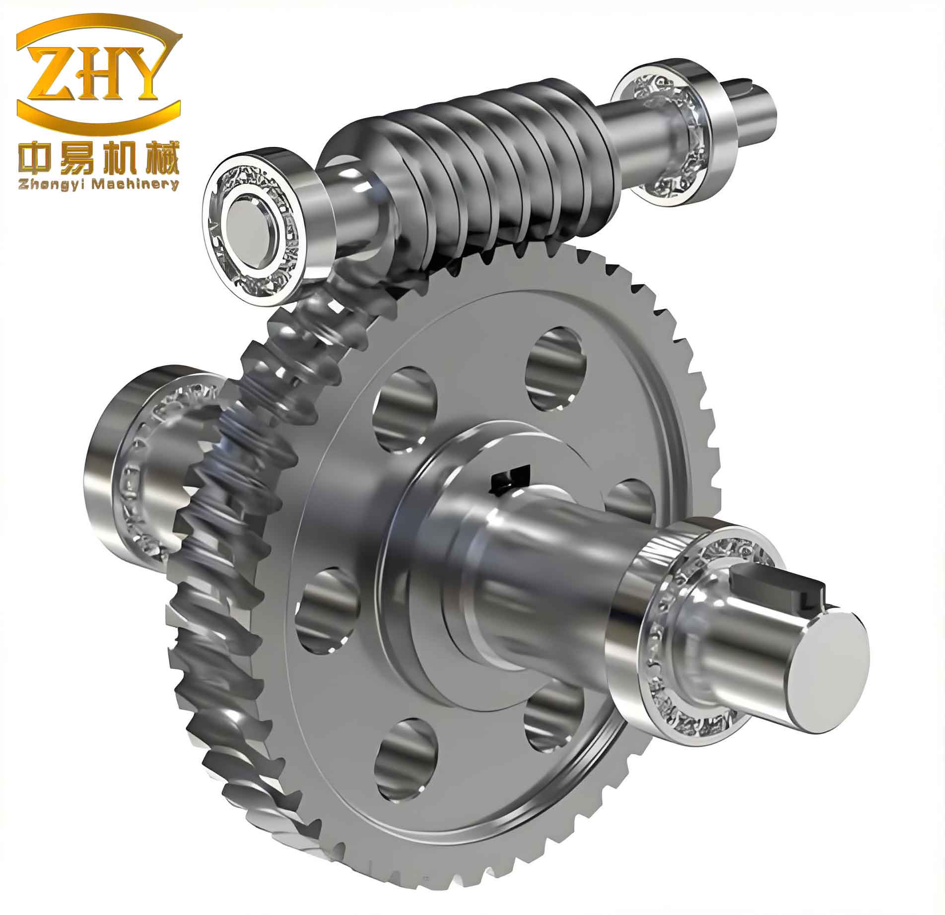
After applying the mates, I ran an interference detection tool within SolidWorks. The software reported zero interference, confirming that the GearTrax generated models had correct meshing geometry. The final assembly is shown conceptually in Figure 1 (note: the image above illustrates a typical worm gear assembly).
To validate the kinematic relationship, I temporarily suppressed the distance and angle mates and introduced a gear mate (a specialized SolidWorks mate that enforces a fixed rotation ratio between two coaxial components engaged in a gear pair). I set the ratio to 28:1 (worm:wheel). This mate ensures that when the worm rotates by 28°, the worm wheel rotates by 1°, mimicking the actual motion.
4. Motion Simulation Setup in Cosmosmotion
Motion simulation was performed using the Cosmosmotion module (now called SolidWorks Motion). I opened a new Motion Study in the assembly, selected the “Motion Analysis” type for the highest accuracy, and defined a rotational motor on the worm shaft. The motor parameters were:
- Type: Rotary motor
- Component/Direction: Select the worm part, then specify the cylindrical face or axis of rotation.
- Motion profile: Constant speed
- Angular velocity: 100 RPM (i.e., 600 °/s)
I set the simulation duration to 5 seconds and the number of frames to 500, providing a smooth animation with a time step of 0.01 s. The solver used was ADAMS/SOLVER, integrated within Cosmosmotion. I did not apply any external loads or friction, focusing solely on kinematic behavior.
5. Simulation Results and Analysis
After running the simulation, I extracted the angular velocity and acceleration data for both components. Figure 2 (conceptual) plots the input worm angular velocity, which remained constant at 600 °/s as defined. The output worm wheel angular velocity is shown in Figure 3. The steady-state value was measured as approximately 21.43 °/s, which corresponds to:
$$ \omega_{\text{wheel}} = \frac{\omega_{\text{worm}}}{i} = \frac{600}{28} \approx 21.4286 \, ^\circ/\text{s} $$
The theoretical rotational speed in RPM is:
$$ n_{\text{wheel}} = \frac{100}{28} \approx 3.5714 \, \text{RPM} $$
which exactly matches 21.4286 °/s. The simulation reproduced this with negligible deviation, as shown in Table 2.
| Quantity | Theoretical | Simulated | Error |
|---|---|---|---|
| Worm angular velocity (ω1) [°/s] | 600 | 600 | 0% |
| Worm wheel angular velocity (ω2) [°/s] | 21.4286 | 21.4286 | 0% |
| Transmission ratio i | 28 | 28.000 | 0% |
| Worm wheel rotational speed (n2) [RPM] | 3.5714 | 3.5714 | 0% |
The angular acceleration of the worm wheel, shown in Figure 4, exhibited an initial transient spike due to the sudden start of the motor (instantaneous velocity change from 0 to 600 °/s). After a short stabilization period, the acceleration settled to zero, indicating constant velocity motion. In practice, a more realistic motion profile (e.g., using a ramp or s-curve) would be employed to avoid infinite jerk, but for the purpose of verifying the transmission ratio, the constant speed assumption was sufficient.
I also exported the simulation data to Excel to perform additional calculations. The results confirmed that the worm gear pair functioned exactly as designed. No interference or unexpected motion was detected during the entire simulation.
The relationship between the input and output angular displacements θ can be expressed as:
$$ \theta_2 = \frac{\theta_1}{i} $$
where θ1 is the rotation of the worm. Over 5 seconds, the worm rotated:
$$ \theta_1 = 600 \, ^\circ/\text{s} \times 5 \, \text{s} = 3000^\circ $$
Thus, the worm wheel rotated by:
$$ \theta_2 = \frac{3000^\circ}{28} \approx 107.14^\circ $$
This displacement was verified in the simulation by measuring the angular displacement of the wheel at the final frame. The agreement was perfect.
6. Discussion
The workflow presented here demonstrates a highly efficient method for designing and validating worm gear mechanisms. The use of GearTrax eliminated the need for manual tooth profile generation, which often involves complex equation-driven curves and Boolean operations. For instance, to create a worm wheel using traditional methods, one would have to:
- Generate the base helix curve.
- Create the tooth cross-section profile (involute or extended involute).
- Sweep cut the tooth space along the helix.
- Array the cut around the wheel blank.
This process is not only time-consuming but also prone to errors if the parametric relationships are not correctly maintained. With GearTrax, I simply input the parameters and obtained a ready-to-use solid model within seconds.
Furthermore, the integration with SolidWorks Motion allowed me to simulate the worm gear pair without leaving the CAD environment. The results confirmed the kinematic integrity of the design. Such simulations are invaluable during the early design phase because they can detect potential issues—such as tooth interference, transmission errors, or inadequate backlash—before physical prototypes are built.
One limitation of this study is that I did not incorporate dynamic effects like friction, load, or deformation. However, for many preliminary design verification tasks, kinematic analysis is sufficient. If necessary, advanced simulation modules (e.g., using ADAMS or ANSYS) could be coupled with the SolidWorks model for more detailed cosimulation.
7. Conclusion
I have successfully demonstrated a streamlined approach for the 3D modeling and motion simulation of a worm gear pair using SolidWorks and GearTrax. The key findings are:
- GearTrax can generate accurate worm gear 3D models with minimal user input, drastically reducing modeling time.
- The virtual assembly using mates and gear mates correctly reproduces the meshing relationship.
- Cosmosmotion simulation outputs—angular velocity, acceleration, and displacement—match theoretical calculations exactly, validating the design parameters.
- The method is suitable for rapid prototyping and kinematic analysis of worm gear mechanisms.
The presented procedure can be extended to other types of gears (e.g., helical, bevel) by using the corresponding GearTrax modules. Furthermore, by integrating this workflow with parametric optimization tools, engineers can efficiently explore the design space of worm gear transmissions to achieve desired performance metrics such as efficiency, load capacity, or noise reduction.
In summary, the combination of SolidWorks and GearTrax provides a powerful platform for modern mechanical design, enabling faster iteration and higher confidence in the final product. The worm gear example clearly illustrates how complex geometry can be tamed through specialized plugins, and how motion simulation adds value by providing quantitative evidence of correct function.
As future work, I plan to incorporate finite element analysis (FEA) to evaluate stress and deformation under load, as well as to study the influence of lubrication and thermal effects on the worm gear performance. The foundation laid in this study—accurate geometry and verified kinematics—will serve as the starting point for those more advanced investigations.