

Chapter 1: The Basic Working Principle and Structure of Worm Gear
The basic working principle and structure of worm gear, including their shape, size, number of teeth, and how they work together to transmit motion and torque.
Worm Gear: Basic Working Principle and Structure
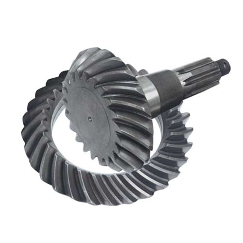
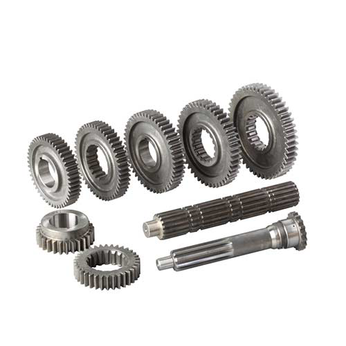
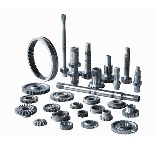
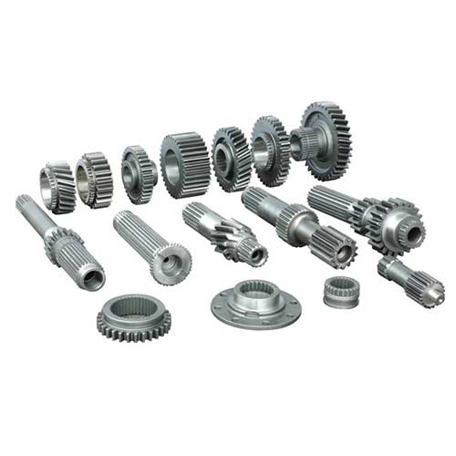
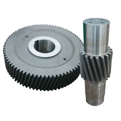
A worm gear is a type of mechanical gear system that consists of two main components: a worm (also known as a worm screw) and a worm wheel (also called a worm gear). The worm is a cylindrical shaft with a helical thread (like a screw), and the worm wheel is a gear with teeth that mesh with the worm’s helical thread. The worm is typically the driving component, while the worm wheel is the driven component.
Shape, Size, and Number of Teeth:
- Worm (Worm Screw): The worm is a cylindrical shaft with a helical thread wrapped around it. The helix angle of the worm’s thread determines the gear ratio between the worm and the worm wheel. The worm typically has only one or a few threads, which means it has relatively few teeth. This leads to a large contact area between the worm and the worm wheel teeth, which can result in high torque transmission.
- Worm Wheel (Worm Gear): The worm wheel is a gear with teeth that mesh with the helical thread of the worm. The number of teeth on the worm wheel is higher than the number of threads on the worm. This design helps achieve a reduction in speed and an increase in torque. The worm wheel’s teeth are usually cut to match the helical shape of the worm’s thread, allowing for smooth engagement and power transfer.
Motion and Torque Transmission:
The working principle of worm gear involves the rotation of the worm shaft to drive the worm wheel. When the worm shaft rotates, its helical thread engages with the teeth of the worm wheel. Due to the helical shape of the thread, the motion of the worm causes the worm wheel to rotate.
The helix angle of the worm’s thread determines the mechanical advantage and gear ratio of the worm gear system. A small helix angle results in a higher gear ratio, providing a significant speed reduction and torque increase. However, worm gear is known for their self-locking property, which means that the worm can prevent the worm wheel from back-driving the system. This characteristic makes worm gear suitable for applications where maintaining a fixed position is important.
Advantages and Applications:
- High Reduction Ratios: Worm gear can achieve high reduction ratios in a compact design, making them useful in applications where a significant speed reduction is required.
- Self-Locking: The self-locking nature of worm gear is advantageous for applications requiring load holding and preventing back-driving.
- Quiet Operation: Worm gear can operate with minimal noise due to the sliding contact between the worm and the worm wheel teeth.
- Applications: Worm gear is commonly used in various industries, including automotive, industrial machinery, conveyor systems, elevators, and other applications that require controlled motion and torque transmission.
Worm gear consist of a worm (worm screw) and a worm wheel (worm gear) that work together to transmit motion and torque. The helical thread of the worm engages with the teeth of the worm wheel, resulting in motion transfer with a significant reduction in speed and an increase in torque. The self-locking property of worm gear is a notable feature that makes them suitable for specific applications.
Chapter 2: The Research on the Application of Worm Gear
Worm gear find applications in various fields due to their unique characteristics and advantages. Let’s explore their roles and advantages in different industries and how they compare to other transmission devices.
1. Industrial Machinery:
Role and Advantages: Worm gear is used in industrial machinery for applications that require high torque and reduction ratios, such as conveyor systems, packaging machinery, and material handling equipment. They provide smooth and reliable motion control while maintaining load holding and preventing back-driving, which is crucial in many industrial settings.
Comparison: In comparison to other transmission devices like spur gears or belt drives, worm gear offer higher torque transmission and load holding capabilities. However, they may have lower efficiency due to sliding friction, making them less suitable for applications where efficiency is a primary concern.
2. Automobiles:
Role and Advantages: Worm gear is employed in automobiles for power steering systems, where they provide a compact and efficient means of translating the rotational motion of the steering wheel into linear motion to assist in steering. Worm gear offer self-locking behavior, ensuring stable and secure steering control.
Comparison: In comparison to other transmission devices like rack and pinion systems, worm gear in power steering provide higher torque output and load holding ability. However, they may be less efficient and require proper lubrication to minimize wear.
3. Aerospace:
Role and Advantages: Worm gear is used in aerospace applications such as actuators and control mechanisms. Their self-locking property is advantageous in scenarios where maintaining a specific position or preventing motion due to external forces is critical. Worm gear can provide precise and stable motion control in aerospace systems.
Comparison: Compared to other transmission devices like helical gears, worm gear is less prone to back-driving and offer better load holding capabilities. However, their lower efficiency may be a concern for some aerospace applications.
4. Power Transmission:
Role and Advantages: Worm gear play a role in power transmission systems for applications like lifting equipment, winches, and conveyor systems. They offer high reduction ratios in a compact design, making them suitable for cases where significant speed reduction and torque multiplication are needed.
Comparison: In contrast to other transmission devices like chain drives, worm gear provide smoother and quieter operation. They also eliminate the need for tensioning systems found in chain drives. However, chain drives may offer higher efficiency in certain situations.
5. Robotics and Automation:
Role and Advantages: Worm gear is used in robotics and automation for applications requiring precise and controlled motion, such as robotic arms and positioning systems. Their self-locking property ensures that the system remains in the desired position when not actively moving.
Comparison: In comparison to alternatives like planetary gears, worm gear offer better load holding and less backlash. However, planetary gears may provide higher efficiency and compactness in some cases.
6. Other Applications:
Worm gear can also be found in various other applications like escalators, medical devices, and material testing equipment, where their self-locking behavior and ability to provide controlled motion are advantageous.
Worm gear find applications in industrial machinery, automobiles, aerospace, power transmission, robotics, and more. Their unique advantages include high torque transmission, self-locking behavior, load holding capabilities, and smooth motion control. However, they may have lower efficiency compared to some other transmission devices. The choice between worm gear and other transmission devices depends on the specific requirements of each application, balancing factors such as torque, efficiency, compactness, and load holding.
Chapter 3: The Historical Evolution and Development Process of Worm Gears
The historical evolution and development of worm gear can be traced back to ancient times, where rudimentary screw mechanisms were used for various purposes. Over centuries, worm gear have evolved from simple mechanical devices to sophisticated components integrated into modern technology. Here’s an overview of their historical progression:
Ancient Times to Medieval Period:
- The earliest forms of worm gear were likely simple screw mechanisms used for lifting and moving heavy objects.
- Ancient civilizations, such as the Greeks and Romans, used screw threads in various applications.
Middle Ages and Renaissance:
- During the Middle Ages and the Renaissance, screw mechanisms were further developed for various engineering applications, including presses, windlasses, and water-raising devices.
- The mechanical advantages of screw threads and their ability to transmit motion over distance were recognized.
18th and 19th Centuries:
- The industrial revolution saw significant advancements in engineering and manufacturing.
- Worm gear were applied in machinery for industrial processes, such as textile manufacturing and milling.
- The development of standardized screw threads and manufacturing techniques contributed to the widespread use of worm gear.
20th Century:
- In the early 20th century, advancements in materials, machining, and gear design led to improved worm gear technology.
- Worm gear found applications in various industries, including automotive, aerospace, and industrial machinery.
- The self-locking property of worm gear made them suitable for applications requiring holding force and safety, such as elevators and lifts.
Modern Times:
- The latter half of the 20th century and beyond saw further refinement of worm gear technology.
- Computer-aided design (CAD) and simulation tools revolutionized gear design and analysis, enabling precise optimization and virtual testing.
- Advances in materials science and manufacturing techniques improved gear quality, strength, and durability.
- Worm gear became integral components in a wide range of applications, from power generation to robotics.
Recent Advances:
- In recent years, additive manufacturing (3D printing) has opened new possibilities for designing complex worm gear geometries and prototypes.
- Digital manufacturing techniques and simulation tools allow for more accurate and efficient gear design and testing.
- Integration with Industry 4.0 concepts, such as IoT-enabled condition monitoring, has enhanced the performance and reliability of worm gear systems.
Throughout history, worm gear have evolved from simple screw mechanisms to sophisticated components integrated into diverse applications. The development of materials, manufacturing processes, and design methodologies has contributed to their widespread use and improved performance, making worm gear an essential part of modern technology.
Chapter 4: The Performance Parameters of Worm Gear
The key performance parameters of worm gear and how they impact the overall performance and efficiency of the system:
1. Transmission Ratio (Gear Ratio):
The transmission ratio of a worm gear system is the ratio of the number of teeth on the worm wheel to the number of threads on the worm. It determines the speed reduction and torque multiplication achieved by the gear system. A higher transmission ratio results in greater speed reduction and torque increase.
Impact on Performance: A higher transmission ratio is beneficial when high torque is required at the output, but it may also lead to lower efficiency due to increased sliding friction between the worm and the worm wheel teeth.
2. Efficiency:
Efficiency in a worm gear system refers to the ratio of output power to input power, taking into account losses due to friction, heat, and other factors. Worm gear typically have lower efficiency compared to other gear types (such as spur gears or helical gears) due to sliding friction between the worm and worm wheel teeth.
Impact on Performance: Lower efficiency means that a portion of the input power is lost as heat, which can limit the overall effectiveness of the system. In applications where high efficiency is crucial, worm gear might not be the best choice.
3. Torque Transmission Ability:
Worm gear is known for their ability to transmit high torque, especially in applications where the worm wheel has multiple teeth engaged with the worm’s thread. The helix angle of the worm’s thread influences the torque transmission capability.
Impact on Performance: The torque transmission ability of worm gear makes them suitable for applications requiring high torque output, such as lifting heavy loads or providing high torque at low speeds.
4. Backlash:
Backlash refers to the clearance or play between the mating teeth of the worm and worm wheel. It can lead to lost motion and reduced precision in the gear system.
Impact on Performance: Excessive backlash can result in inaccuracies and reduced repeatability in motion control applications. Minimizing backlash is important in applications where precise positioning is required.
5. Self-Locking Property:
Worm gear exhibit a self-locking behavior due to the helical angle of the worm’s thread. This means that the worm can prevent the worm wheel from rotating the system backward.
Impact on Performance: The self-locking property is advantageous in applications where load holding and preventing back-driving are critical, such as in lifting equipment or safety mechanisms.
6. Lubrication and Wear:
Proper lubrication is essential for the smooth operation and longevity of worm gear. Lubrication helps reduce friction and wear between the mating surfaces.
Impact on Performance: Inadequate lubrication can lead to increased friction, wear, and decreased efficiency. Proper maintenance and lubrication are necessary to ensure optimal performance and longevity.
The performance parameters of worm gear, including transmission ratio, efficiency, torque transmission ability, backlash, self-locking property, and lubrication, play crucial roles in determining the overall performance and efficiency of the system. Designers and engineers must carefully consider these parameters based on the specific requirements of the application to achieve the desired balance between torque, speed, efficiency, precision, and load-holding capabilities.
Chapter 5: The Design Principles of Worm Gear
Designing a suitable worm gear transmission system involves understanding the design principles of worm gear, calculating geometric parameters, and analyzing load-bearing capacity. Here’s a step-by-step guide to designing a worm gear transmission system based on actual needs:
1. Understand Design Principles:
A. Basic Geometric Parameters:
- Determine the desired speed ratio (gear ratio) between the worm and the gear.
- Calculate the worm’s lead, which is the distance the worm advances along its axis in one complete rotation.
- Choose the module (pitch) of the gear to ensure proper tooth engagement.
B. Center Distance and Worm Diameter:
- Calculate the center distance between the worm and the gear to achieve the desired gear ratio.
- Determine the worm diameter to ensure adequate contact length for load distribution.
C. Tooth Profile and Pressure Angle:
- Choose the tooth profile for both the worm and gear (commonly, worm gear use an enveloping worm thread and a helical gear tooth profile).
- Decide on the pressure angle (typically 20°) for smooth engagement and load distribution.
2. Load Analysis and Capacity Calculation:
A. Load Calculation:
- Determine the applied loads (torque and axial force) and operating conditions (speed, direction) on the worm gear system.
- Analyze the dynamic loads, shock loads, and thermal effects the system may experience.
B. Load Distribution:
- Evaluate how the worm tooth transmits load to the gear tooth.
- Calculate the contact stress and analyze the load distribution along the contact line.
C. Load-Bearing Capacity:
- Refer to manufacturers’ catalogs or standards to determine the permissible load-carrying capacity of worm gear.
- Check the calculated load against the gear’s capacity to ensure safe operation.
3. Lubrication and Efficiency:
A. Lubrication Requirements:
- Choose the appropriate lubricant and lubrication method to minimize friction and wear.
- Ensure proper lubrication for efficient operation and heat dissipation.
B. Efficiency Considerations:
- Estimate the mechanical efficiency of the worm gear system, accounting for friction and losses.
- Consider efficiency trade-offs between different design choices.
4. Axial Thrust and Backlash:
A. Axial Thrust Management:
- Analyze and manage axial thrust resulting from the helix angle of the worm thread.
- Use thrust bearings or other mechanisms to counteract axial forces.
B. Backlash Control:
- Determine the desired amount of backlash (clearance) between the worm and gear to prevent binding while ensuring proper engagement.
5. Material Selection:
A. Worm Material:
- Choose a material for the worm that offers good wear resistance and compatibility with the gear material.
B. Gear Material:
- Select a material for the gear with adequate strength, wear resistance, and compatibility with the worm material.
6. Assembly and Alignment:
- Ensure proper alignment and assembly of the worm gear system to avoid misalignment, binding, or premature wear.
7. Noise and Vibration Control:
- Analyze noise and vibration issues and incorporate design features (such as gear tooth modifications) to minimize them.
8. Iterative Design and Validation:
- Use computer-aided design (CAD) and simulation tools to model the system and evaluate its performance.
- Perform iterative design and analysis to optimize gear parameters and ensure reliable operation.
9. Safety Factors and Standards:
- Apply appropriate safety factors to design parameters to ensure the system’s reliability and durability.
- Adhere to relevant industry standards and guidelines for gear design.
Designing a suitable worm gear transmission system involves a comprehensive understanding of the principles, calculations, and considerations mentioned above. Collaboration with experienced mechanical engineers and gear specialists is recommended to ensure that the designed worm gear system meets the specific needs of the intended application and operates safely and effectively.
Chapter 6: The Manufacturing Process of Worm Gear
The manufacturing process of worm gear involves several steps, from material selection to heat treatment, to ensure the desired quality, durability, and performance. Here’s a detailed overview of the manufacturing process and its impact on worm gear quality and lifespan:
1. Material Selection:
- Choose materials with good wear resistance, strength, and heat treatability.
- Common materials include alloy steels (e.g., AISI 4140, 8620), stainless steels, and bronze.
- Material selection influences gear strength, wear resistance, and overall lifespan.
2. Machining Process:
A. Worm Blank Preparation:
- Start with a cylindrical or disk-shaped piece of material for the worm.
- Turn and center the blank to the desired dimensions.
B. Hobbing (Cutting Worm Teeth):
- Use a hobbing machine to cut worm teeth.
- The hob’s threads shape the worm teeth by gradually removing material.
- The hob rotates while the workpiece advances axially.
C. Grinding (Optional):
- After hobbing, grinding may be employed to improve tooth surface finish and accuracy.
- Grinding ensures precise tooth profiles and a smooth surface for efficient engagement.
3. Heat Treatment:
- Heat treatment enhances gear hardness, strength, and wear resistance.
- Typical heat treatment processes include carburizing and quenching followed by tempering.
- Proper heat treatment minimizes distortion and ensures uniform material properties.
4. Surface Treatment (Optional):
- Surface treatments like nitriding or coating (e.g., TiN) can further enhance wear resistance and surface hardness.
- Nitriding introduces nitrogen to the surface, forming hard nitride compounds.
5. Inspection and Quality Control:
- Conduct dimensional inspection, tooth profile measurement, and hardness testing.
- Verify that the gear’s dimensions, tooth profiles, and material properties meet specifications.
6. Lubrication Considerations:
- Proper lubrication is crucial for worm gear performance and longevity.
- Choose appropriate lubricants and consider lubrication methods to reduce friction and wear.
Impact on Quality and Lifespan:
A. Material Selection:
- Proper material selection ensures the gear can handle loads and wear without premature failure.
- Inadequate materials can lead to poor wear resistance, tooth failure, or even catastrophic gear failure.
B. Machining Precision:
- Accurate machining ensures proper tooth engagement and minimizes friction.
- Precise machining reduces the risk of premature wear, noise, and inefficiency.
C. Heat Treatment:
- Proper heat treatment enhances gear strength and hardness, reducing wear and increasing lifespan.
- Inadequate or improper heat treatment can result in premature fatigue or tooth failure.
D. Surface Treatment:
- Surface treatments enhance wear resistance, reducing the risk of pitting and wear.
- A well-treated surface increases gear longevity and reliability.
E. Quality Control:
- Rigorous inspection and quality control ensure that the gear meets design specifications.
- Poor quality control can result in variations in tooth profiles, dimensions, and material properties.
The manufacturing process significantly influences the quality and lifespan of worm gear. Proper material selection, precision machining, appropriate heat treatment, and thorough quality control all contribute to producing durable and reliable worm gear capable of withstanding the demands of their intended applications.
Chapter 7: The Analysis of the Causes of Worm Gear Failure
Worm gear, like any mechanical components, can experience faults and wear over time due to various factors. Understanding these potential causes of faults and implementing proper maintenance and repair practices can help extend the service life and reliability of worm gear. Here are some common faults, their causes, and maintenance/repair strategies:
1. Tooth Wear and Damage:
- Cause: Repeated meshing and sliding between worm and gear teeth.
- Maintenance/Repair: Regular inspection for signs of wear, pitting, or damage. Replace worn components. Proper lubrication to minimize wear.
2. Tooth Breakage or Chipping:
- Cause: Overloading, shock loads, or misalignment.
- Maintenance/Repair: Check load conditions and alignment. Replace broken or chipped teeth. Address root causes to prevent recurrence.
3. Backlash Variations:
- Cause: Inadequate manufacturing precision, wear, or misalignment.
- Maintenance/Repair: Regularly check and adjust backlash. Address misalignment issues. Maintain manufacturing quality.
4. Lubrication Issues:
- Cause: Inadequate or improper lubrication.
- Maintenance/Repair: Use proper lubricants and lubrication methods. Maintain correct lubrication levels and intervals.
5. Axial Thrust Problems:
- Cause: Excessive axial loads, misalignment, or improper thrust bearing arrangement.
- Maintenance/Repair: Analyze axial loads and choose suitable thrust bearing arrangements. Align the system properly.
6. Noise and Vibration:
- Cause: Misalignment, poor gear meshing, or inadequate lubrication.
- Maintenance/Repair: Analyze noise and vibration sources. Address misalignment, improve gear meshing, and ensure proper lubrication.
7. Corrosion and Contamination:
- Cause: Environmental factors, improper storage, or inadequate sealing.
- Maintenance/Repair: Implement proper sealing and protection. Regular cleaning and inspection. Address corrosive environments.
8. Fatigue Failure:
- Cause: Cyclic loading, shock loads, or inadequate material or heat treatment.
- Maintenance/Repair: Analyze load conditions. Choose suitable materials and heat treatment. Address load-related issues.
9. Misalignment:
- Cause: Installation errors or wear over time.
- Maintenance/Repair: Properly align the worm and gear. Monitor alignment regularly.
10. Improper Lubrication: – Cause: Incorrect lubricant type, insufficient lubrication, or contaminated lubricant. – Maintenance/Repair: Use recommended lubricants and follow lubrication guidelines. Regularly monitor and replace lubricants.
11. Overheating: – Cause: Excessive friction, inadequate cooling, or heavy loads. – Maintenance/Repair: Improve lubrication, check cooling systems, and address load-related issues.
12. Cracks or Structural Damage: – Cause: Material defects, manufacturing issues, or excessive stresses. – Maintenance/Repair: Inspect for cracks or structural damage. Replace damaged components. Analyze root causes.
Extending Service Life and Reliability:
A. Regular Inspection:
- Conduct routine visual and dimensional inspections to identify signs of wear or damage.
B. Lubrication Management:
- Use proper lubricants and ensure regular lubrication to minimize friction and wear.
C. Load Management:
- Avoid overloading the system and ensure proper gear design for the intended loads.
D. Alignment and Installation:
- Properly align and install the worm gear system to prevent misalignment-related issues.
E. Maintenance Schedule:
- Develop and follow a maintenance schedule based on manufacturer recommendations and operational conditions.
F. Training and Expertise:
- Ensure maintenance personnel are trained in proper gear maintenance and repair techniques.
G. Continuous Monitoring:
- Implement condition monitoring techniques, such as vibration analysis, to detect early signs of issues.
By addressing potential faults, performing regular maintenance, and taking preventive measures, you can extend the service life and reliability of worm gears, minimizing downtime and ensuring efficient and safe operation.
Chapter 8: Deeply Understand the Working Mechanism of Worm Gear
Understanding the motion characteristics and mechanical behavior of worm gear systems is crucial for gaining insight into their working mechanism. Here’s an overview of the key aspects to consider:
1. Motion Characteristics:
A. Gear Ratio:
- Worm gear provide high gear ratios in a compact design.
- A single revolution of the worm results in a smaller fraction of revolution of the gear, leading to speed reduction.
B. Self-Locking and Backdrive:
- Worm gear exhibit self-locking behavior, where the load cannot drive the worm backward due to the friction angle between the worm and gear teeth.
- This self-locking property is advantageous in applications where holding a load is critical.
- However, it also means worm gear are not very efficient for backdriving.
C. Efficiency and Sliding Contact:
- Worm gear are efficient in transmitting motion and torque but tend to have higher friction losses due to sliding contact between the worm and gear teeth.
- Helix angle of the worm teeth contributes to axial forces and sliding friction.
D. Tooth Engagement and Contact:
- Worm gear engagement occurs over a line contact between a single tooth on the gear and multiple teeth on the worm.
- This concentrated contact area can lead to high stress and localized wear.
2. Mechanical Behavior:
A. Load Distribution and Tooth Contact:
- Load distribution in worm gears is uneven due to the line contact.
- Proper gear design aims to distribute the load over several teeth to prevent premature wear and tooth failure.
B. Axial Thrust:
- Due to the helix angle of the worm thread, axial thrust is generated along the worm’s axis.
- This thrust must be managed using thrust bearings or other mechanisms to prevent gear axial movement.
C. Wear and Lubrication:
- Sliding contact and high contact stresses can lead to wear and pitting on gear teeth.
- Proper lubrication is essential to reduce friction, wear, and heat generation.
D. Load Capacity and Efficiency:
- Worm gear offer high torque transmission capability but may have lower mechanical efficiency compared to other gear types.
- The efficiency is influenced by factors like friction, lubrication, tooth profile, and gear quality.
E. Thermal Effects:
- Sliding friction generates heat, which must be managed to prevent overheating and premature failure.
- Adequate lubrication and proper gear design help dissipate heat effectively.
F. Noise and Vibration:
- Sliding contact and axial thrust can contribute to noise and vibration in worm gear systems.
- Gear design modifications and proper lubrication can help minimize noise and vibration.
Understanding these motion characteristics and mechanical behaviors helps designers and engineers make informed decisions when selecting, designing, and implementing worm gear systems. It also guides efforts to optimize gear performance, reliability, and lifespan while addressing potential challenges and limitations.
Chapter 9: International and Industry Standards Related to Worm Gear
Several international and industry standards provide guidelines and specifications for the design, manufacturing, and usage of worm gear. These standards ensure that worm gear systems meet quality, safety, and performance requirements. Here are some key standards related to worm gear:
1. ISO Standards:
A. ISO 53:
- ISO 53 provides general specifications for worm gear systems, including terms, definitions, and basic principles.
B. ISO 1328-1:
- ISO 1328-1 specifies the general principles for cylindrical gears, including worm gear. It covers geometry, tolerances, and definitions.
C. ISO 1328-2:
- ISO 1328-2 provides methods for calculating the load capacity and surface durability of worm gear.
D. ISO/TR 14521:
- ISO/TR 14521 offers guidelines for the application and selection of worm gear systems, including design considerations and load capacity calculations.
2. AGMA Standards:
A. AGMA 6022-C93:
- AGMA 6022-C93 provides information on the design, application, and lubrication of worm gear sets.
B. AGMA 6034-A06:
- AGMA 6034-A06 covers the design and selection of materials for worm gear, including materials, heat treatment, and hardness requirements.
C. AGMA 6044-A06:
- AGMA 6044-A06 offers guidelines for the lubrication of worm gear, including lubricant selection and application methods.
3. DIN Standards:
A. DIN 3974-7:
- DIN 3974-7 provides guidelines for calculating load capacity and permissible contact stress for worm gear.
B. DIN 3975:
- DIN 3975 covers calculation methods for the load capacity of worm gear sets.
4. ANSI/AGMA Standard:
A. ANSI/AGMA 6123-B06:
- ANSI/AGMA 6123-B06 provides guidelines for the design, selection, and application of worm gear.
5. JIS Standards:
A. JIS B 1703:
- JIS B 1703 specifies the design, dimensions, and tolerances for worm gear.
B. JIS B 1711:
- JIS B 1711 covers the calculation of load capacity for worm gear.
These standards offer comprehensive guidelines for the design, manufacturing, and usage of worm gear, ensuring that they are manufactured to high-quality standards, perform reliably, and meet safety requirements. Engineers and manufacturers can refer to these standards to ensure their worm gear systems are designed, produced, and operated in accordance with recognized industry best practices.