By combining the basic involute equation with the involute in the gear machining coordinate system, the involute curve equation of helical gear in machining can be obtained as follows:
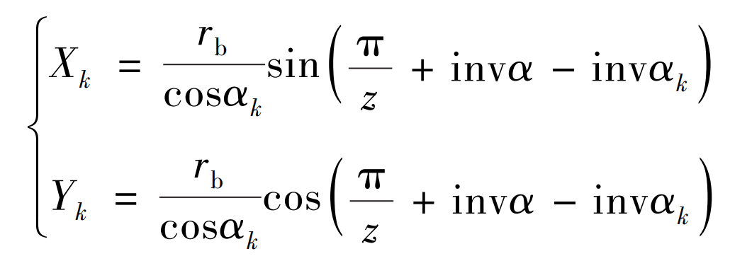
In the formula: RB is the radius of the base circle; α K is the pressure angle of any point K on the involute; Z is the number of teeth; α Is the pressure angle; Inv () is an involute function.
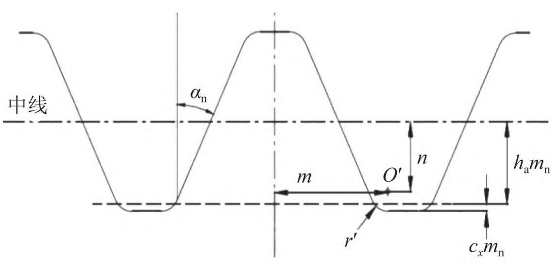
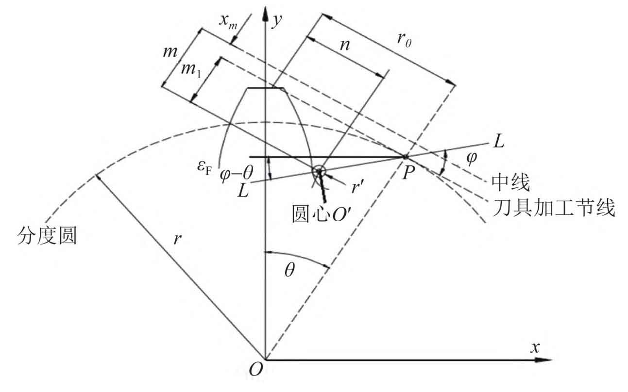
The tooth profile of the strip cutter for machining helical gear is shown in Figure 1. The parameter relationship expression of the rack cutter for machining the tooth root transition curve is as follows:
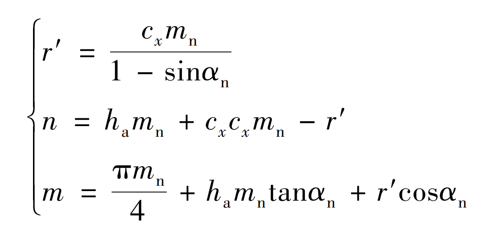
In the formula: R ‘is the fillet radius of the tooth root of the machined gear; N is the distance from the center o ‘to the center line; M is the distance from the center o ‘to the centerline; Mn is the normal modulus; CX is the radial displacement coefficient; α N is the normal pressure angle; Ha is the normal addendum height coefficient.
The tooth root curve of the gear processed by the tool is shown in Figure 2. According to the involute equation and tooth profile parameters, the parameter equation of tooth root transition curve can be obtained as follows:
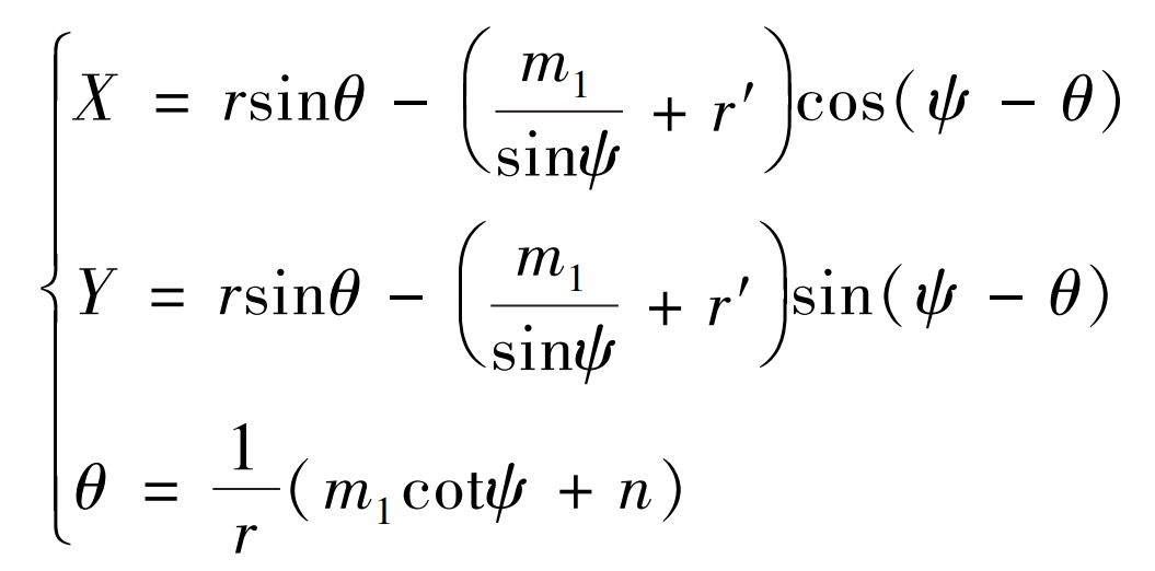
In the formula: ψ Is the included angle between ll and the tool processing pitch line; θ Is an auxiliary variable. The basic geometric parameters of helical gear are shown in the table.
| Parameters and units | Measurement |
| Number of teeth Z1 / Z2 | 18/27 |
| Normal modulus Mn / mm | 4 |
| Normal pressure angle α n/ (°) | 20 |
| Helix angle β / (°) | 12 |
| Tooth width B / mm | 20 |
| Normal addendum height coefficient ha | 1 |
| Radial displacement coefficient CX | 0.25 |
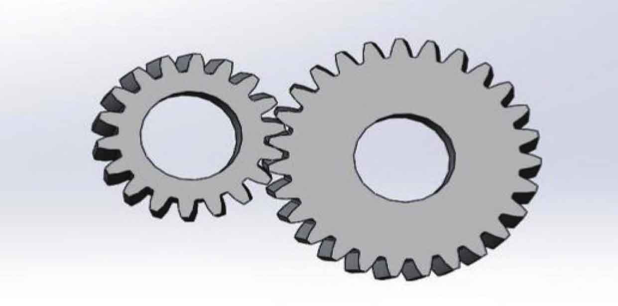
According to the tooth profile curve, tooth root curve and relevant parameters of helical gear, the three-dimensional modeling of helical gear is imported into SolidWorks, as shown in Figure 3.