
UG is a software that integrates CAD/CAM/CAE, with powerful functions and the ability to easily construct complex entities and shapes. UG (CAD) provides a comprehensive modeling process and is a mechanical design software that directly models from explicit entities, surfaces, and parameterization. It has the characteristics of high innovation, good quality, high efficiency, and full functionality. It is one of the most widely used 3D modeling software and has unique advantages in increasingly complex product development and design. Based on the geometric parameters of the highly modified cylindrical gear calculated above, parameterized 3D modeling of the cylindrical gear is carried out using UG (CAD) software.
1.Modeling of cylindrical gear pinions
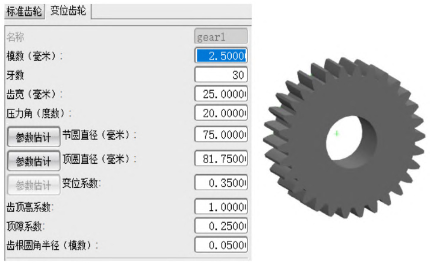
In the UG toolbar, select cylindrical gear modeling, and the Involute Gear Modeling dialog box will pop up. Use the [Create Gear] command to select [Shifted Gear]. In the dialog box for creating cylindrical gears, the modeling parameters involved include: module, number of teeth, tooth width, pressure angle, pitch diameter, top circle diameter, modification coefficient, addendum height coefficient, top clearance coefficient, and root fillet radius, Input the calculated geometric parameters into the corresponding positions, and click OK to generate a cylindrical gear pinion as shown in Figure 1.
2.Modeling of cylindrical gear wheels
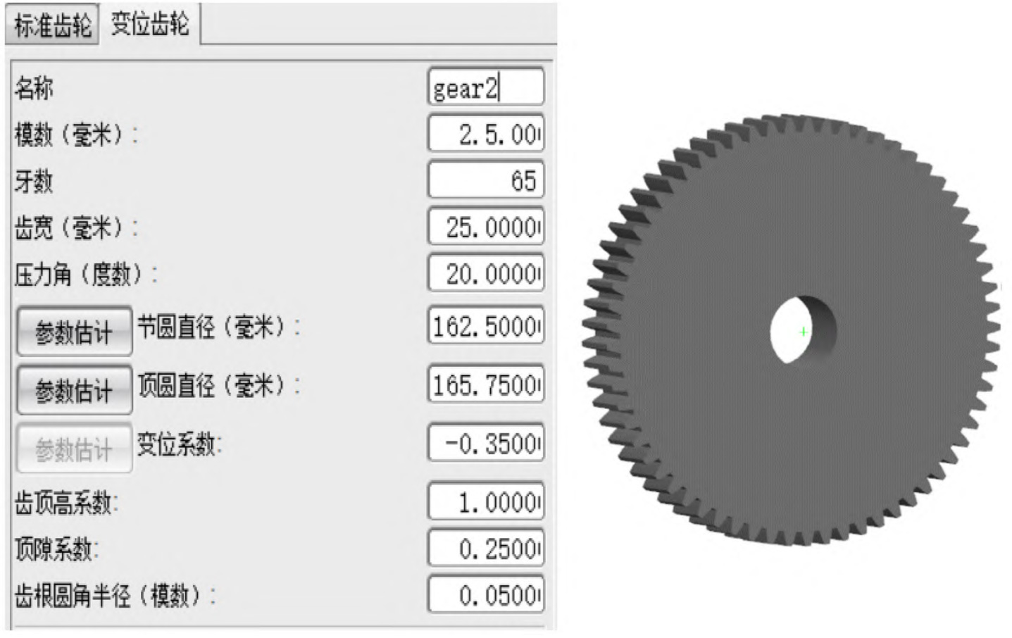
It is the same as the modeling method of the cylindrical gear pinion mentioned above. Select Tools>Cylindrical Gear Modeling, click the [Create Gear] option, select [Displacement Gear], and enter the name, module, number of teeth, pressure angle and other parameters of the cylindrical gear wheel into the dialog box to get the three-dimensional modeling model of the cylindrical gear wheel, as shown in Figure 2.
3.Meshing of pinion and wheel cylindrical gears
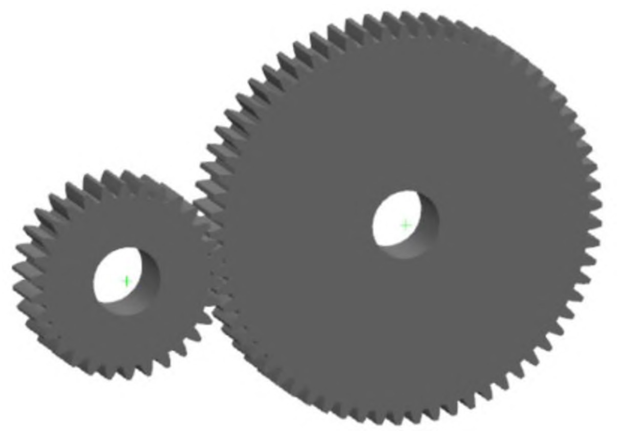
In the gear modeling, select 【 Cylindrical Gear Modeling 】. In the pop-up 【 Involute Cylindrical Gear Modeling 】 dialog box, select 【 Gear Meshing 】 for the operation method of the cylindrical gear. In the cylindrical gear meshing dialog box, select the gear pinion of the cylindrical gear as the driving wheel, the gear wheel of the cylindrical gear as the driven wheel, and set the centerline vector to the Y-axis, as shown in Figure 3.