
Pro/E is a parametric modeling software, which can establish the three-dimensional model of spur gear through parameterization, which greatly improves the universality of the model. When the parameters of spur gear change, the three-dimensional model can be changed directly by modifying the parameters. The three-dimensional model of spur gear can be established by the following method.
First, define the relevant parameters of spur gear through “Tools > parameters” menu: modulus (m), number of teeth (z) and pressure angle( α)、 Width (b), crest height coefficient (hax), root height coefficient (HFX), crest clearance coefficient (Cx), displacement coefficient (x). Then, enter the table relationship under the “relationship” menu, and draw the graduation circle, base circle, tooth top circle and tooth root circle respectively by using the parameter relationship.
| Graduation circle | d=m*Z |
| Base circle | db=d*cos α |
| Addendum height | ha=(hax+x)*m |
| Root height | hf=(hax+cx-x)*m |
| Addendum circle | da=d+2*ha |
| Root circle | df=d-2*hf |
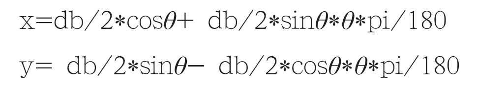
Draw the involute tooth profile and angle with parametric equation θ Is a variable from 0 to 45 ° and introduces a change in parameter t from 0 to 1, then θ = 45*t。 The involute equation can be expressed as follows:
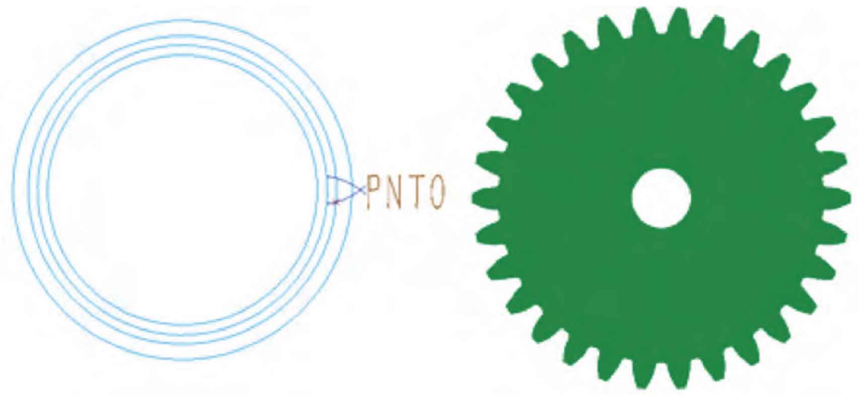
The intersection of involute and indexing circle is pnt0, as shown in the figure. The reference plane dtm1 is made through the point pnt0 and the axis, and the included angle between the reference plane dtm2 and dtm1 is γ/ 2. Make a mirror involute with dtm2 as the mirror surface, and then use the tooth root circle and tooth top circle to make a complete tooth section sketch. By stretching the tooth width B with the “stretch” command, a tooth model can be generated, and the tooth array can be used as a complete spur gear model, as shown in the figure. After the model is built, the spur gear models with different parameters can be obtained by changing the set parameter values.
The key to the modeling of modified spur gear lies in the angle between the datum dtm2 and dtm1 γ/ 2. Determination of. Set the center angle corresponding to the tooth thickness of the indexing circle as γ, Then the included angle of the mirror plane is γ/ 2. If the spur gear is a standard constant position spur gear, then γ= 180/Z。 When there is displacement of spur gear, the tooth thickness of indexing circle is s = π M / 2 + 2 xmtan α, Then:
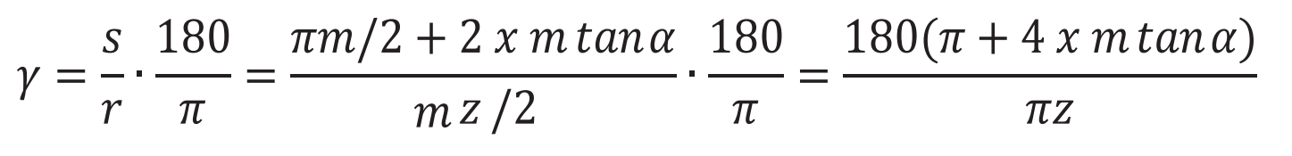
Some existing literatures do not consider the influence of modification coefficient and can not be correctly used in the modeling of modified spur gear γ It is a formula containing modification coefficient, which is the key to distinguish modified spur gear from standard spur gear modeling. After the modeling of single gear model is completed, the large and small gears are assembled according to the meshing position and installation requirements by establishing the assembly body, so as to obtain the three-dimensional model of spur gear pair.