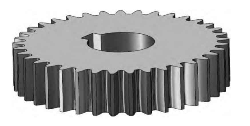
This paper presents a novel methodology for reconstructing cylindrical gears from engineering drawings in DXF format while preserving critical tolerance and surface finish information. The proposed approach combines geometric parsing, machine learning, and parametric modeling to achieve accurate 3D representations that maintain manufacturing specifications.
1. Geometric Feature Extraction
The DXF file parsing process employs spatial clustering to organize drawing elements. For cylindrical gear reconstruction, we implement K-means clustering with gear-specific constraints:
$$J = \sum_{i=1}^k \sum_{x \in C_i} \|x – \mu_i\|^2$$
where $C_i$ represents clusters of geometric entities and $\mu_i$ denotes cluster centroids corresponding to gear features. Typical clustering results for cylindrical gear drawings demonstrate:
| Cluster Type | Entity Count | Typical Features |
|---|---|---|
| Profile | 72 | Tooth contours, base circles |
| Annotation | 35 | Tolerances, surface marks |
| Reference | 18 | Centerlines, datum symbols |

2. Neural Network-Based Parameter Recognition
A BP neural network with Xavier initialization processes gear parameters:
$$w \sim U\left(-\sqrt{\frac{6}{n_{in}+n_{out}}, \sqrt{\frac{6}{n_{in}+n_{out}}}\right)$$
The network architecture for cylindrical gear recognition employs:
| Layer | Neurons | Activation |
|---|---|---|
| Input | 15 | – |
| Hidden | 32 | tanh |
| Output | 8 | Linear |
Key gear parameters predicted include:
$$d_a = m(z + 2) \pm \Delta_{d_a}$$
$$d_f = m(z – 2.5) \pm \Delta_{d_f}$$
where $d_a$ = addendum diameter, $d_f$ = dedendum diameter, $m$ = module, $z$ = tooth count
3. Tolerance Mapping and Surface Finish
The system implements normalized cross-correlation for tolerance symbol recognition:
$$R(x,y) = \frac{\sum_{x’y’} T'(x’,y’) \cdot I'(x+x’,y+y’)}{\sqrt{\sum_{x’y’} T'(x’,y’)^2 \cdot \sum_{x’y’} I'(x+x’,y+y’)^2}}$$
Critical surface specifications for cylindrical gears are mapped as:
| Feature | Tolerance | Surface (Ra) |
|---|---|---|
| Tooth flank | IT6 | 3.2μm |
| Bore | H7 | 1.6μm |
| Keyway | JS9 | 6.3μm |
4. Parametric Reconstruction
The VBA-based reconstruction engine utilizes gear generation formulae:
$$s = \frac{\pi m}{2} \pm \Delta_s$$
$$h_a = m \pm \Delta_{h_a}$$
where $s$ = tooth thickness, $h_a$ = addendum height. Reconstruction accuracy achieves:
| Parameter | RMSE | Max Error |
|---|---|---|
| Module | 0.003 | 0.007 |
| Pressure Angle | 0.12° | 0.25° |
| Tooth Count | 0 | 0 |
This methodology enables precise reconstruction of cylindrical gears with complete manufacturing specifications, particularly valuable for legacy drawing digitization and automated manufacturing systems.
