
Before the solid modeling of helical gear in Pro/E software environment, firstly, the coordinates of discrete data points calculated in MATLAB software environment are imported into Pro/E software environment. These discrete coordinate points can form a series of curves in Pro/E.
The main steps of transforming the discrete point coordinates into the tooth surface of helical gear: first, insert the curve – self file, select the default coordinate system, and then select the required IBL file, the cubic spline curve composed of discrete points is obtained in the graphics window (that is, one side of the helical gear composed of curves is obtained), and the import method of the other side of the helical gear is the same. According to the theoretical knowledge of helical face gear, the teeth of face gear are plane in the axis direction (upper bottom surface and lower bottom surface), and the front and rear surfaces (at its near end surface and far end surface) are cylindrical.
According to these characteristics of the helical gear, in order to avoid the separation of the gear tooth from the unprocessed blank of the helical gear (i.e. at the inner diameter of the proximal end and the outer diameter of the distal end), a tooth groove of the helical gear is formed by a series of curves on the helical gear blank, and then the tooth groove is arrayed in the circumferential direction of the helical gear, The solid model of helical gear is obtained.
The main steps of helical gear modeling are:
(1) First, select the “boundary blending” item in the “insert” menu, then select the two side curves that make up the tooth slot one by one to obtain its surface (i.e. the two sides of the tooth slot), then select the curves that make up the upper and lower bottom surfaces to obtain the surface (i.e. the upper and lower bottom surfaces), and finally select the near end and far end curves to obtain its surface (front and back).
(2) Secondly, merge the six groups of surfaces that make up the cogging. That is, in the edit menu, select merge. Make it a whole of six groups of surfaces.
(3) Achieve a alveolar resection. Select “materialize” and “remove material” to complete the removal of a tooth groove, so as to obtain a tooth groove of helical gear.
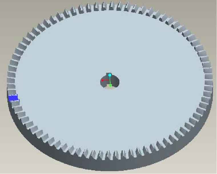
(4) The complete helical gear is obtained by arraying the slots. First select the “array” option, then select the “axis”, “Z” slot, and copy the “360 / Z” array along the circumferential direction to obtain the helical gear solid model. As shown in the figure.