The dynamic excitation caused by the time-varying meshing comprehensive stiffness of helical gear system is one of the most important dynamic excitation forms in helical gear transmission. In the transmission process of helical gear system, the change of the number of meshing teeth, the elastic deformation of teeth and the error of teeth lead to the change of meshing stiffness, resulting in the dynamic meshing force of teeth. Therefore, determining the time-varying meshing stiffness of helical gear transmission system is one of the important problems in the study of helical gear dynamics.
Calculation flow of comprehensive meshing stiffness of helical gear. The specific steps are as follows: 1) calculate the meshing stiffness per unit contact line length of the end face of a single pair of helical gears according to the helical gear parameters or the helical gear calculation model; 2) The meshing stiffness of the unit contact line length of the normal surface of a single pair of helical gears is calculated from the meshing stiffness of the unit contact line length of the end face of a single pair of helical gears; 3) Determine the relationship between the angle of helical gear and the length of contact line; 4) The meshing stiffness of single pair of teeth is obtained by calculating the meshing stiffness of contact lines with different lengths of single pair of teeth; 5) The comprehensive meshing stiffness of helical gear is synthesized from the meshing stiffness of single pair of teeth.
The meshing stiffness per unit contact line length of single pair of teeth on the end face of helical gear can be calculated by relevant helical gear software or theoretical formula. The theoretical formula is calculated as follows:
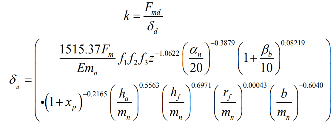
Where: FMD is the load per unit contact line length at different positions on the tooth profile of the tooth end face, F1, F2 and F3 are the load point position coefficient, radial position coefficient and axial position coefficient respectively, e is the elastic modulus, Mn is the normal modulus of helical gear, HA and HF are the tooth top height and tooth root height respectively, XP is the tooth top modification coefficient, RF is the fillet radius of tooth root, β B is the helix angle of the base circle, α N is the normal pressure angle.
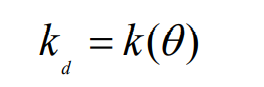
The meshing stiffness per unit contact line length of single pair of teeth on the end face of helical gear is expressed as the rolling angle of helical gear θ And stiffness KD, then:
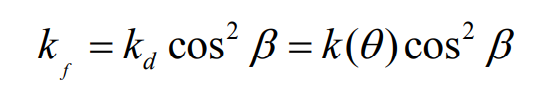
According to the geometric relationship of helical gear, the meshing stiffness per unit contact line length of single pair of teeth on the normal surface of helical gear can be calculated:
For a single tooth, when the helical gear enters meshing, the length of the contact line increases from zero to the maximum length of the contact line with the rotation time of the helical gear, and remains constant for a period of time; When the helical gear pair starts to withdraw from engagement, the length of the contact line gradually decreases. When it withdraws from engagement, the length of the contact line is zero, as shown in the figure. The geometric relationship between the rolling angle and the contact line length in the figure can be expressed as:
Where: B is the effective contact tooth surface width of helical gear; β B is the helix angle of driving wheel base circle; Is the axial coincidence degree of helical gear.
The meshing stiffness expression of contact lines with different lengths of single pair of teeth is:
Among them; θ Is is the rolling angle corresponding to the starting point of the I contact line; θ If is the rolling angle corresponding to the end point of the I contact line;
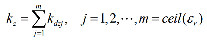
Then the meshing stiffness of a single pair of teeth is obtained from the meshing stiffness of contact lines with different lengths of a single pair of teeth:
Based on the meshing stiffness of a single pair of teeth and the coincidence relationship of helical gears, the comprehensive stiffness of helical gear system is obtained as follows: