
The dynamic transmission error of spiral bevel gear system is related not only to the mechanical and geometric properties of spiral bevel gear, but also to the spiral bevel gear support system. The coupling vibration and elastic deformation of shaft and bearing have a certain influence on the dynamic transmission error. The shaft and bearing of the small wheel are added into the model, the convex surface (meshing surface) of the large wheel is the real tooth surface, and the model of spiral bevel gear system is shown in Figure 1.
1. Establishment of finite element model of spiral bevel gear system
The main differences between the establishment of finite element model and the establishment of meshing finite element model of single pair spiral bevel gear pair above are the boundary conditions of small wheel, the change of load and the simplification of bearing. During pretreatment, the position of the small wheel boundary condition needs to be changed to the shaft. When the bearing is meshed directly, the calculation results are difficult to converge. Therefore, without considering the friction of the bearing, the bearing is simplified into a spring, and the spring stiffness is obtained according to the data. When modeling, the connecting element is used to simulate the spring stiffness of the bearing, which is obtained by the stiffness calculation method of the elastic rod. The cross-sectional area of the elastic rod is:
Where: A is the cross-sectional area of the connecting unit (M2), K is the stiffness of the connecting unit (n / M), and l is the length of the connecting unit (m); E is the elastic modulus of the connecting unit (n / m2).
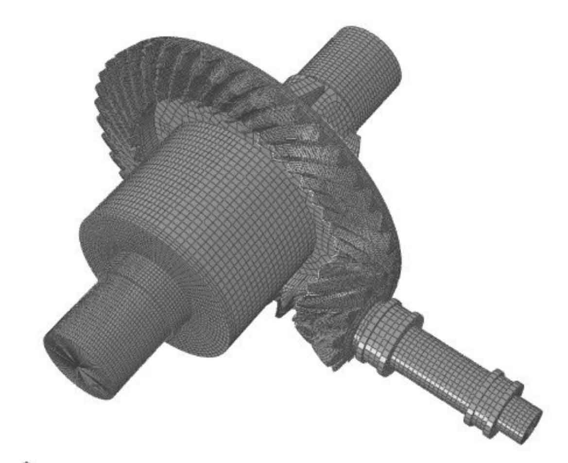
Figure 2 shows the finite element model of spiral bevel gear with small wheel support system.
2. Calculation results and analysis
2.1 Transmission error curve of spiral bevel gear system
After the calculation, extract the historical output variables of large and small wheels in ABAQUS to obtain the transmission error curve as shown in Figure 3. The three curves represent the dynamic transmission error curves under three different loads. By observing the above figure, it is found that: ① the greater the load, the greater the absolute value of transmission error, and the more intense the fluctuation at the initial stage of meshing. ② The transmission error presents a process from violent fluctuation to gradual stability. At the initial stage of meshing, the curve amplitude is large. After the small wheel rotates about 0.4 rad, the transmission error is in a relatively stable state. ③ The transmission error curve reflects the large vibration of spiral bevel gear system in the initial meshing stage.
2.2 Comparison of dynamic transmission error
Under the action of load of 150 n · m, the transmission error curve with elastic support system is compared with the dynamic transmission error curve of single pair spiral bevel gear pair meshing on the real tooth surface of large wheel. The results are shown in Fig. 4.