1. Tooth surface contact analysis of spiral bevel gear
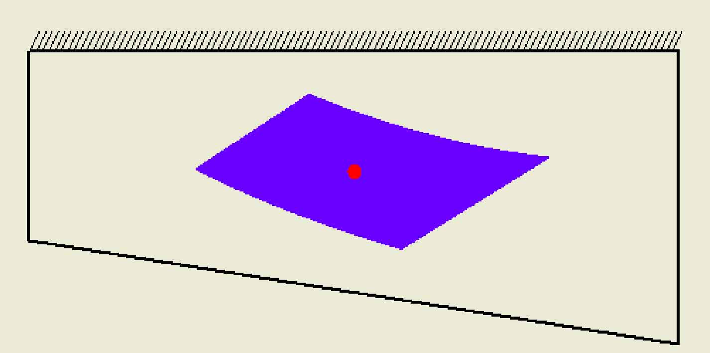
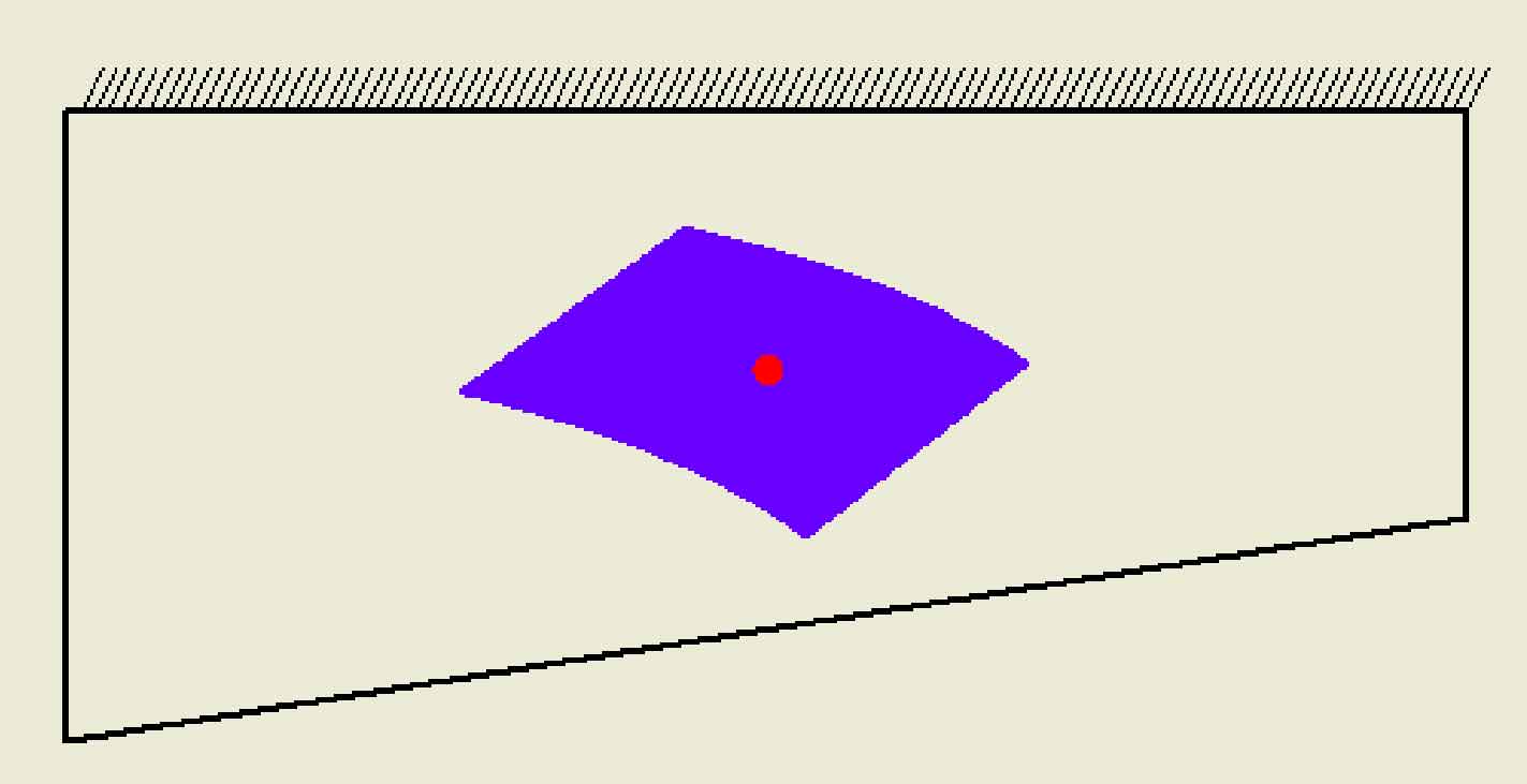
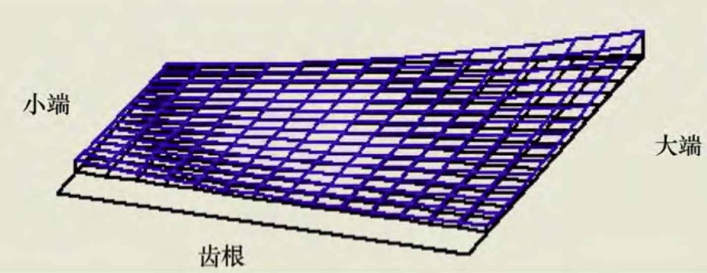
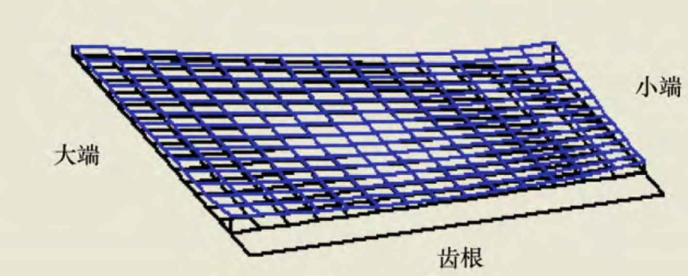
Based on the above theoretical methods, the whole process design software of spiral bevel gear is developed, which can design and calculate the geometric parameters of gear blank, machine tool adjustment parameters, tooth surface meshing analysis of spiral bevel gear (transmission error, contact area, tooth surface mismatch), etc. In order to verify the effectiveness of this method and the whole process design software of spiral bevel gear, a 7 × 43 hypoid gear pair as an example, the basic design parameters of the gear pair and the machine tool adjustment parameters of the gear pair are calculated. The simulation results of the tooth surface contact analysis of the gear pair are shown in Figure 1 ~ 3, in which the transmission error curve is shown in Figure 1. It can be seen from the figure that the maximum value of the working face value of the transmission error amplitude is 12 “and the non working face value is 13”; The contact area diagram is shown in Fig. 2, and its shape is inner diagonal; The tooth surface mismatch diagram of spiral bevel gear is shown in Figure 3, which can intuitively see the tooth surface mismatch of small gear.
2. Loading contact analysis
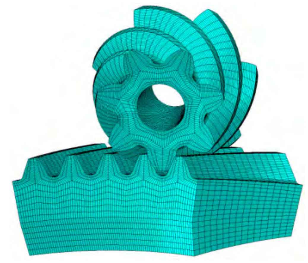
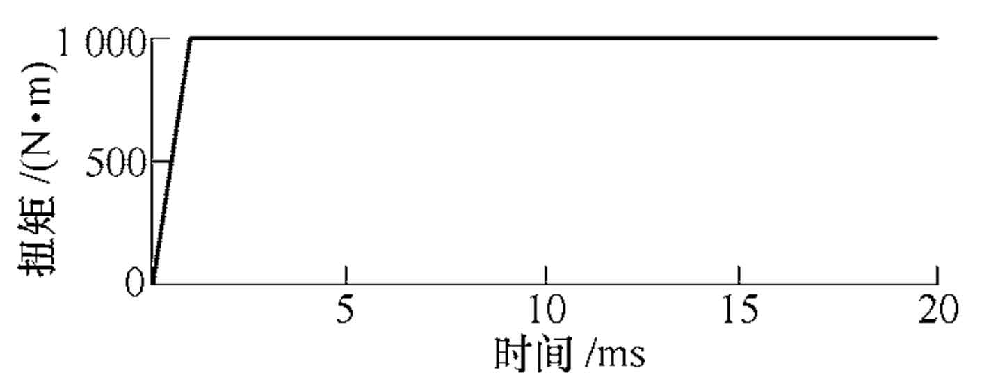
The tooth loading contact analysis of the gear pair is carried out by using ABAQUS simulation software. The finite element analysis model of hypoid gear pair is shown in Figure 4. The set working condition is: load 1000 n • m and speed 1000 R / min. In order to reduce the impact generated in the start-up stage and realize the purpose of stable loading, a two-step loading method is used. The first step is the slope load, and the load is gradually increased to 1000 n · m in 0 ~ 0.001 s; The second step is step load. When the load reaches the maximum value, the load is constant. The load time relationship curve is shown in Figure 5.
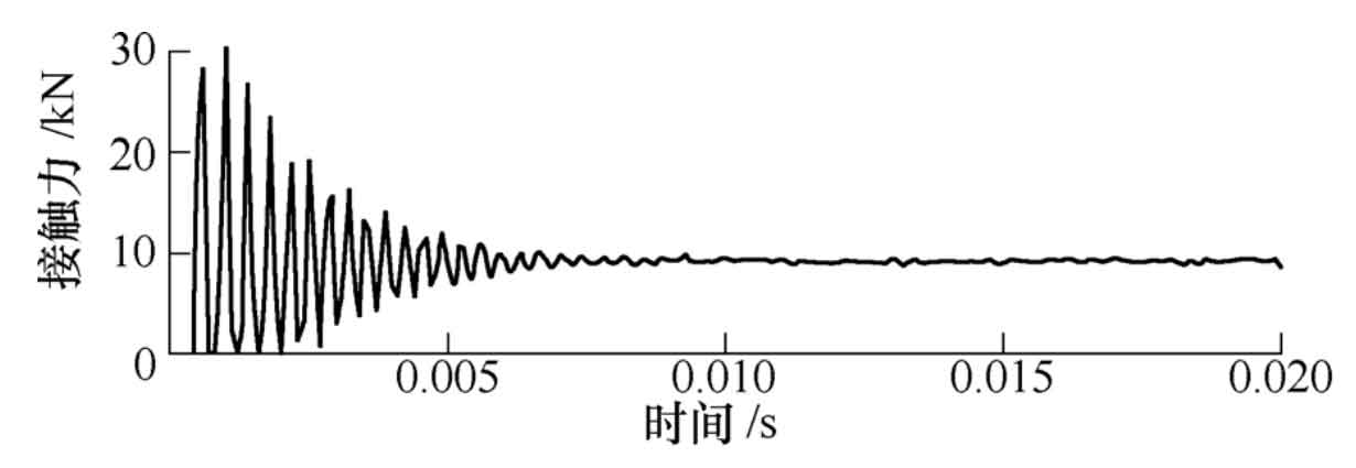
In order to save the simulation time, only five teeth of the large wheel model are intercepted. The Mises stress nephogram of a certain instantaneous of the large wheel and the small wheel are shown in Fig. 6 and Fig. 7 respectively. It can be seen from the comparison between the loading contact analysis results in Fig. 6 and the TCA simulation results in Fig. 2 that the contact mark in the Mises stress nephogram is equivalent to the contact ellipse of a certain instantaneous in TCA; Because the contact area diagram obtained by TCA simulation is calculated under the condition of no load, and the contact ellipse in Mises stress cloud diagram is simulated under the condition of load, the contact ellipse of the latter is much larger than the former, and the contact area formed by the latter can almost cover the whole tooth surface of spiral bevel gear; The contact area in TCA is inner diagonal, and the contact path is from small end tooth root to large end tooth top, which is completely consistent with the results of loading contact analysis. The curve of the contact force on the tooth surface of spiral bevel gear with time is shown in Fig. 8.
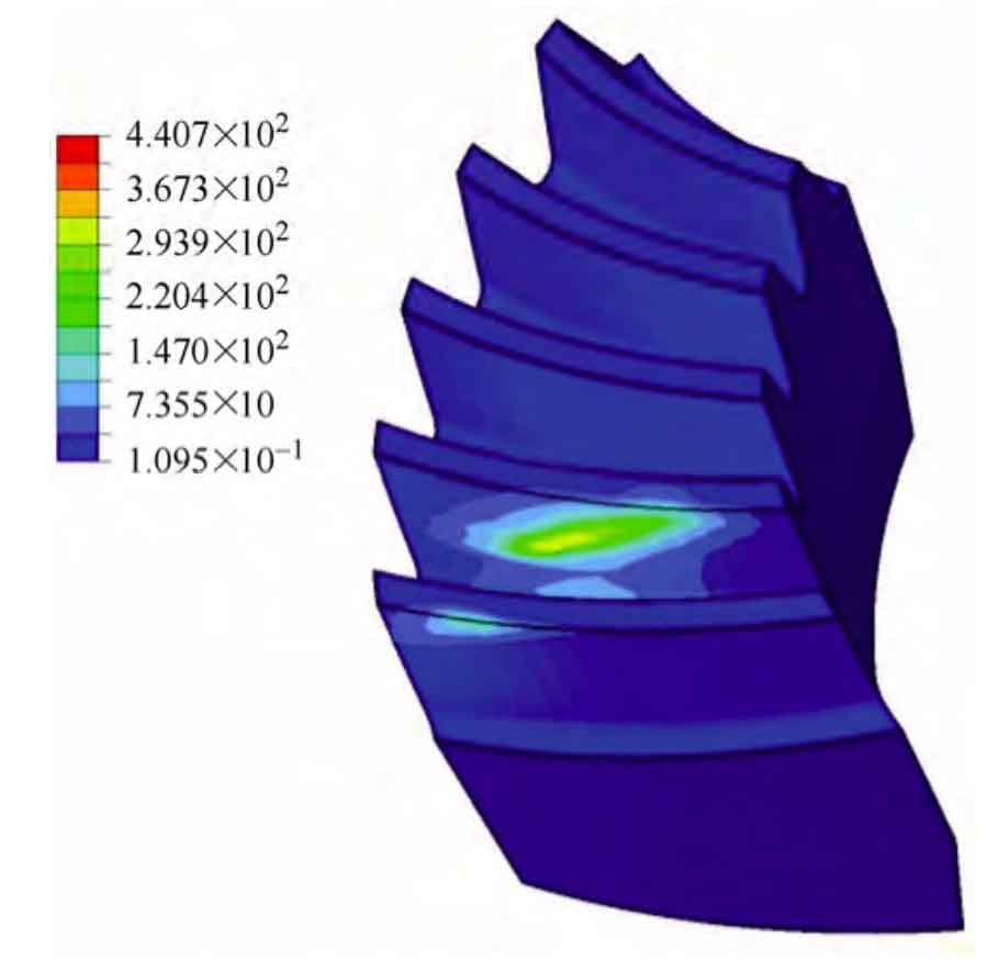
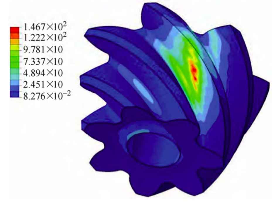
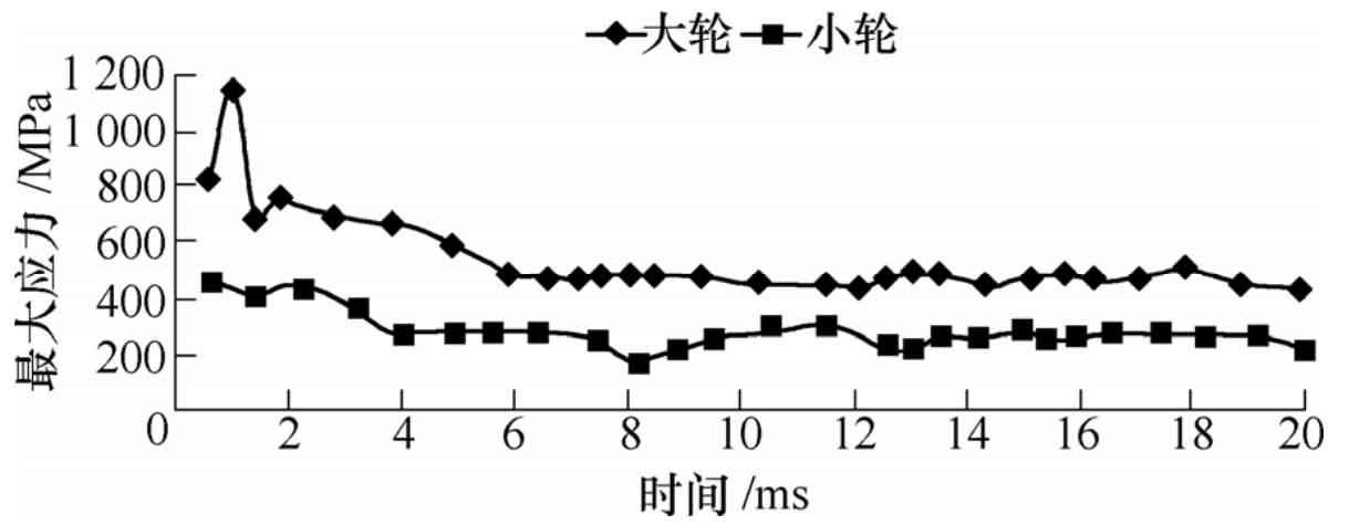
The maximum contact force is 30 kn. It can be seen from the figure that the stress value fluctuates greatly due to the impact force in the time period of 0 ~ 7 ms; After 7 ms, the load gradually stabilized, and the tooth surface contact force of spiral bevel gear fluctuated about 9 kn, with a relatively small fluctuation range. The relationship curve between the maximum Mises stress and time of large wheel and small wheel is shown in Figure 9, which is similar to the curve of contact force on the tooth surface of spiral bevel gear. The Mises stress value fluctuates greatly at the initial stage of load application. When the load is stable, the maximum stress value of large wheel fluctuates between 438.8 ~ 505.5 MPa and the maximum stress value of small wheel fluctuates between 175.6 ~ 300.6 MPa. The simulation results show that the gear pair transmission is stable, the contact stress distribution on the tooth surface of spiral bevel gear is reasonable, and there are no meshing defects such as stress concentration and edge contact.
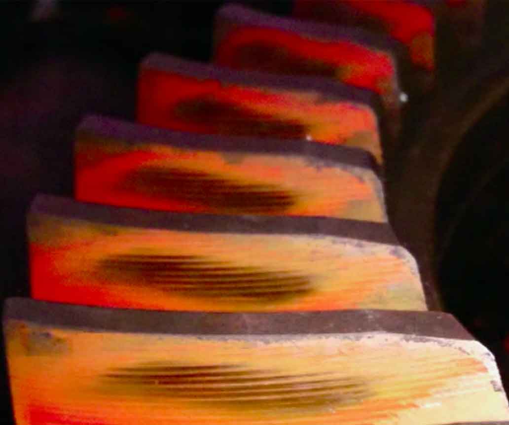
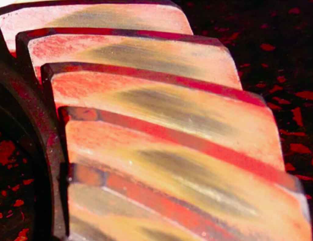
3. Processing test
In order to further prove the effectiveness of the method in this paper, a hypoid gear pair is cut by using the above design and machine tool adjustment parameters, and the contact area is checked on the rolling inspection machine. The inspection results are shown in FIG. 10. It can be seen from Fig. 10 that the shape, size and contact path direction of the contact area are basically consistent with the tooth surface contact analysis results of spiral bevel gear (Fig. 2), and the meshing quality of the gear pair is good, which verifies the correctness of this method.