
In recent years, the precision forming of spur gears in China has been greatly developed, but there are still many deficiencies in the forming process. Based on the research of scholars at home and abroad, this paper summarizes the forming process of spur cylindrical gear, mainly including the following processes. For different gear parts, these processes can be used alone or in combination. Scholars at home and abroad have improved and innovated based on these processes.
1. Traditional closed forging
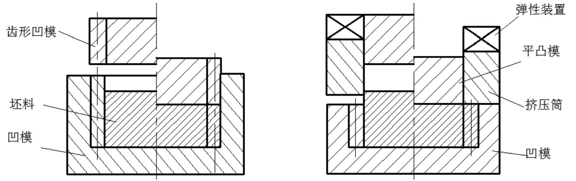
The closed forging of spur gears is mainly divided into two types: the guide type shown in Figure 1 (a), and the die is guided by the tooth surface of punch and die; The clamping type shown in Figure 1 (b) has a toothless punch with an elastic device to fix the blank. The research shows that under the same load, the forming effect of structure a is better than that of structure B, but it is difficult to realize the rapid movement of punch; The clamping type adopts flat punch, which overcomes this disadvantage. At the same time, both schemes have the disadvantages of difficult filling of tooth shape angular gap, large load and low die life.
2. Floating die
The floating die technology of spur gear is to change the friction between die and blank that hinders metal flow into positive friction that promotes metal flow, so that the blank is easy to fill the angular gap of die cavity.
As shown in Figure 2, there are three die structures of closed die forging. Figure 2 (a) shows the structure of the fixed die. The upper punch goes down, the lower punch and the female die are stationary, the metal surface is pressed and upsetting and extrusion flow occurs, the metal flows downward relative to the female die, the friction force of the female die acting on the blank is upward, and the downward flow of metal is difficult, which is unfavorable to the filling of the lower die cavity.
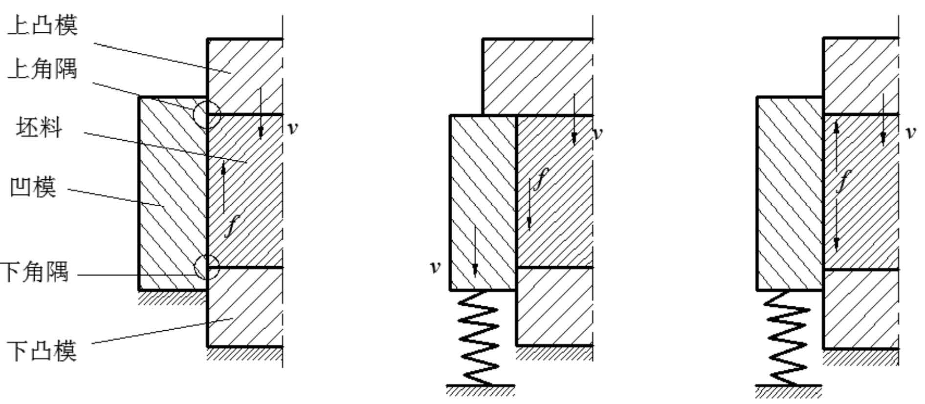
Figure 2 (b) shows the structure of the moving die. The lower punch is fixed, the upper punch drives the female die to move downward at a speed of V, and the spring is compressed and deformed. Because the blank is between the upper and lower dies, the internal metal flow speed is approximately decreasing from V to 0, and the blank moves upward relative to the female die. Therefore, the downward friction force given by the female die to the blank can promote the downward flow of metal, which is conducive to the filling of the lower die cavity.
Figure 2 (c) shows the structure of free floating die. The upper punch moves downward at speed V, the lower punch does not move, the female die floats freely, and the blank speed is T-shaped along the axial direction. Because the upper part of the blank is in contact with the upper punch, the speed is very high, which drives the concave die to move downward. It can be inferred that there is an isokinetic surface in the axial direction of the metal, so that the flow speed of the metal is equal to the moving speed of the concave die. At this time, the blank is stationary relative to the concave die. According to the principle of mechanics, the isokinetic surface is at the middle surface.
3. Split forging
The working pressure of die forging includes ideal deformation resistance, friction resistance and excess work resistance. The ideal deformation resistance can be expressed by the formula:
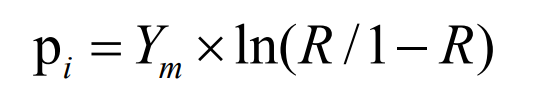
Where:
YM – Nominal flow stress;
R – relative area reduction rate;
Relative area reduction rate:
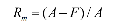
Where:
A – total surface area of die forgings;
F – free surface area of die forging in die cavity.
During die forging, because the free surface area of the workpiece in the die cavity decreases and the RM value increases, if the increase of RM can be controlled, the working pressure may be reduced. In closed die forging, the relative area reduction rate becomes 1. Theoretically, the metal needs infinite working pressure to completely fill the die cavity under this condition. If an overflow port is set at the unimportant part of the forging, it will work when the required shape is fully filled, which can alleviate the sharp rise of working pressure. This method can improve the stress of the die bore, improve the service life of the die, accommodate excess metal and reduce the requirements for blanking accuracy.
According to the above analysis, Mr. Yingming Kudo, a Japanese expert, proposed two diversion measures to reduce the working load during closed die forging. The schematic diagram is shown in Figure 3.
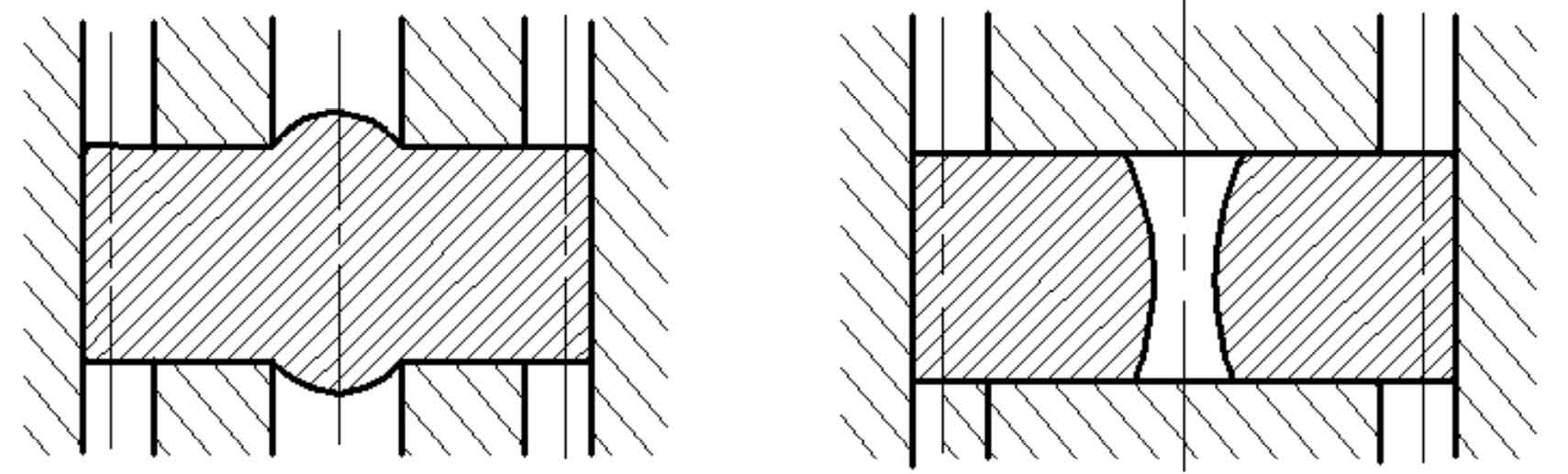
(1) Axial shunt decompression: a shaft like protrusion is added at the center of the pressure bearing surface of the forging to reserve a decompression port for the forming material. Through this setting, not only the purpose of overflow and pressure reduction can be achieved, but also the increase of the reduction rate of the end face of the workpiece and the rise of the pressure peak on the pressure bearing surface can be restrained.
(2) Hole shunt decompression: a decompression hole is reserved in the center of the blank. When the punch is pressed down, the decompression hole shrinks and the material can flow radially to the center to realize the purpose of shunt decompression.
4. Extrusion forming process
Forward extrusion forming process is a kind of cold precision die forging. The extrusion process is the plastic deformation of metal under high stress. Therefore, the cold extrusion parts have dense structure, continuous metal fiber, and the fatigue strength and wear resistance are much higher than those of straight tooth cylindrical gears.
Extrusion forming can obtain high forming accuracy and surface roughness. In addition, it can also obtain residual compressive stress on the tooth surface and prolong the service life of spur gear. However, the metal is extruded from cylindrical blank, with large metal deformation, large extrusion pressure and serious die wear. Considering the factors such as die manufacturing size and cold forging press, at present, the forward extrusion process is limited by extrusion deformation rate and is only applied to the processing of small-size gears, but it is feasible as the finishing process after forging spur gears.