
The metal forming force of spur gear is the main consideration basis for determining the die size and structure and selecting forming equipment. The forming loads of three schemes are analyzed.
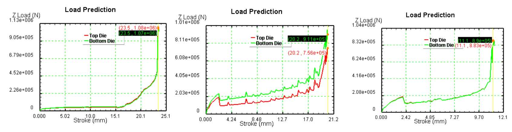
As shown in Figure 1, the travel load curves of the three schemes are shown. From the trend of the curve, the load of the three schemes of spur gear is small at the beginning and rises slowly. When the upper and lower corners of the tooth profile are filled at last, the load rises sharply and reaches the maximum in a short stroke. The maximum load of scheme I is 1080kn. In scheme 2, the loads on the upper and lower punch are different. The load on the lower punch is 911kn greater than that on the upper punch. The maximum load of scheme 3 is 890kn.
From the above analysis, it can be concluded that the three schemes of spur gear will lead to a sharp increase in load in the final stage of forming. In scheme 1, the load required to fill the tooth cavity is the largest, and in scheme 3, the load is the smallest.
Observe the die wear of the three schemes of spur gear, as shown in Figure 2. In scheme 1, the metal flows along the axial direction at the beginning, and finally fills the tooth cavity under the pressure of the upper punch, so the metal flow speed is large and the wear is serious.
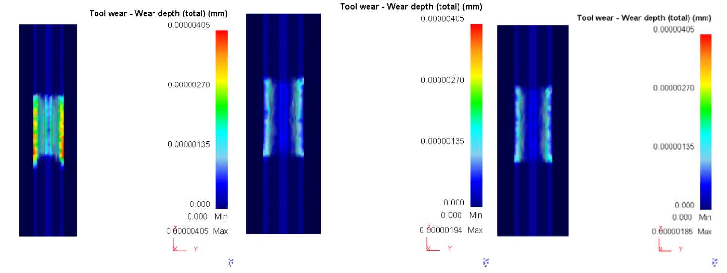
This option can be excluded. The wear of scheme 2 and scheme 3 is relatively small. In scheme 2, the connecting skin is at the bottom, the metal flow distance is long, the flow resistance is large, and the wear is large. In the scheme, the three connecting skins are in the middle, symmetrical up and down, uniform flow, small axial flow distance and relatively small wear.