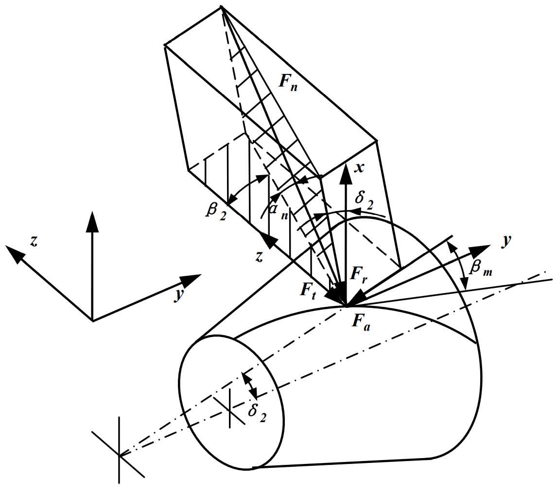
As shown in the figure, the force analysis of the driven gear is carried out. The relative displacement xn of the two spiral bevel gears along the meshing line is:
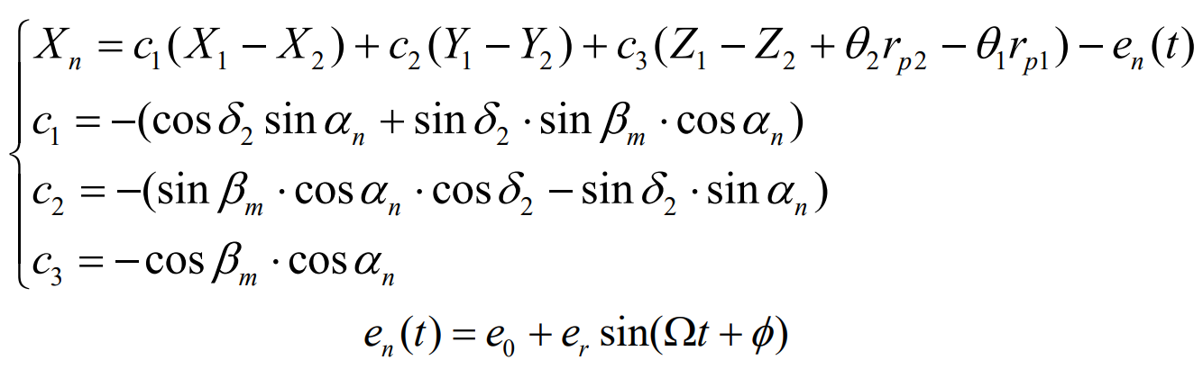
Where, α N is the normal pressure angle; β M is the helix angle at the midpoint; δ 2 is the pitch cone angle of driven wheel; RP1 and RP2 are the meshing point radius of the main and driven wheels respectively; En (T) is the normal static transmission error of the gear pair; Er is transmission error amplitude; E0 is the transmission error constant; Ω is the meshing angle frequency of the gear pair; Φ Is the meshing phase angle of the gear pair.
In the meshing process, the normal load on the driven spiral bevel gear pair and its component forces along each coordinate axis are respectively:
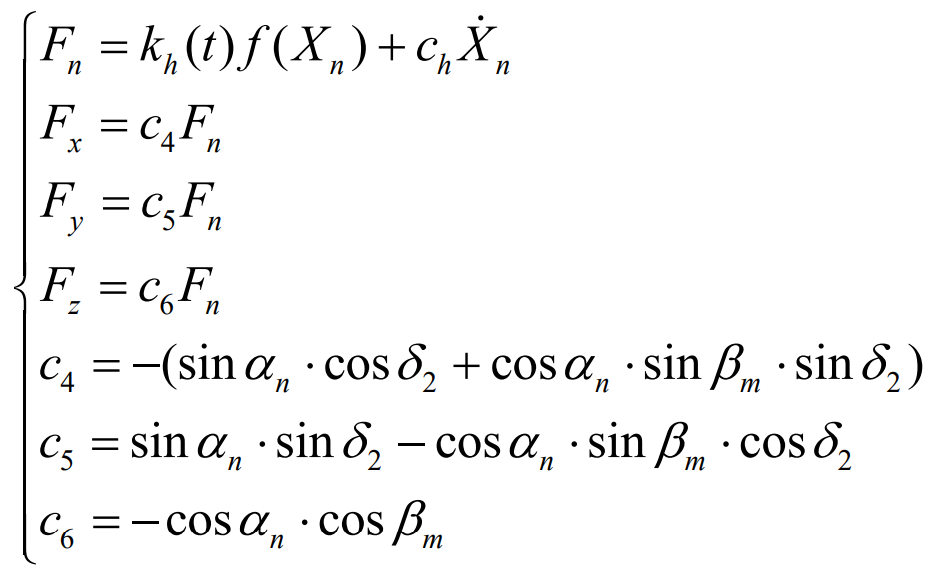
Where, ch is the meshing damping of the gear pair; F (xn) is the meshing tooth side clearance of the gear pair. And:
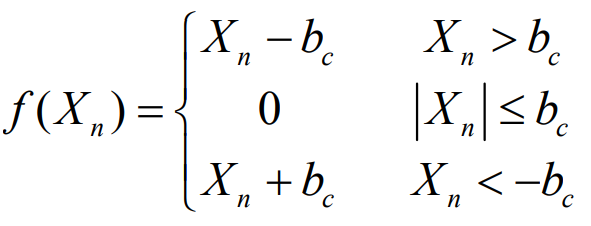
Where BC is half of the normal average meshing clearance.
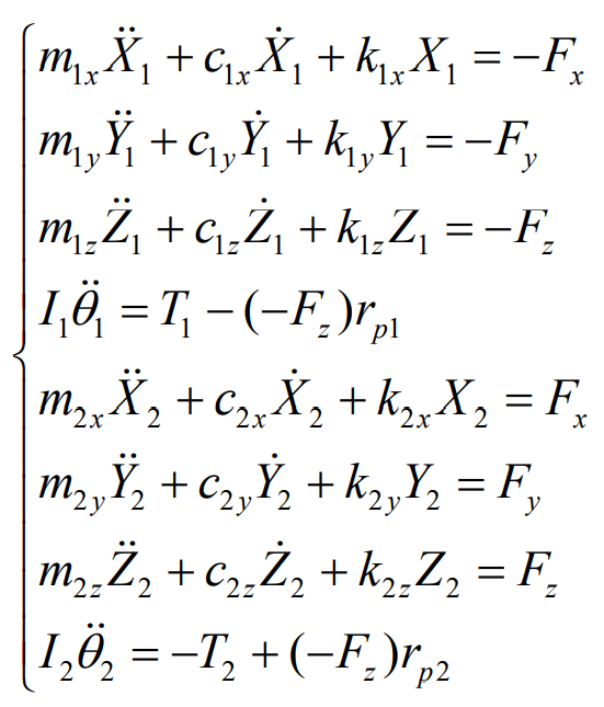
The dynamic differential equation of spiral bevel gear transmission is: