According to the tooth contact analysis principle and gear meshing principle, the machining parameters of hypoid gear are calculated through the established hypoid gear machining coordinate system. According to the tooth surface rotation projection principle, through a certain coordinate transformation relationship, the three-dimensional coordinate points of points on the tooth surface can be obtained.
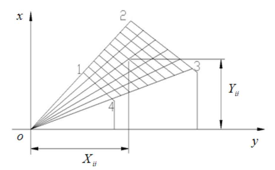
According to the formula, the three-dimensional coordinate points on the tooth surface of hypoid gear correspond to the plane points on the rotating projection plane (hereinafter referred to as plane points) one by one. The mesh nodes can be divided on the rotating projection plane, and then the three-dimensional coordinate points of the tooth surface of hypoid gear can be obtained by using the equation. The mesh node division of hypoid gear tooth surface rotation projection plane is shown in Figure 1. The plane figure in the figure is the projection of the tooth surface, the four vertices are the four vertices on the tooth surface of the hypoid gear, the four boundaries are the four boundary lines on the tooth surface of the hypoid gear, and the points on the figure are the plane coordinate points of the tooth surface of the hypoid gear.
Hypoid gear is studied. The tooth surface of hypoid gear is divided into 5×9 points, which are divided into 4 equal parts in the direction of tooth height and 8 equal parts in the direction of tooth length. The grid node sequence is pi J (I, 1,2… 5 J, 1,2… 9).
In order to obtain the plane coordinate values of the nodes on the plane mesh, the plane coordinate values of the four boundary vertices on the tooth surface of hypoid gear need to be solved first. The calculation formula of the coordinate values of the four boundary vertices is as follows:
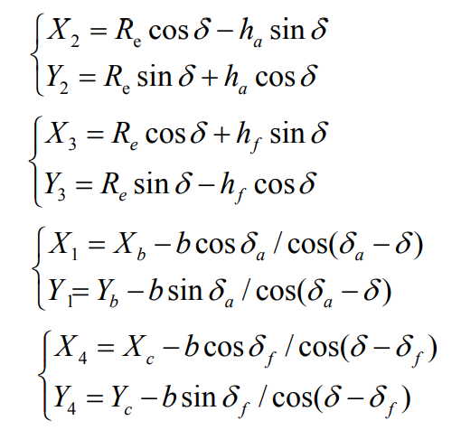
Where, HF is the root height of gear teeth, ha is the top height of gear teeth, δ F – large wheel root cone angle, δ A – cone angle of large wheel surface, δ— Large wheel pitch cone angle, re – large wheel outer cone distance, B – large gear tooth width.
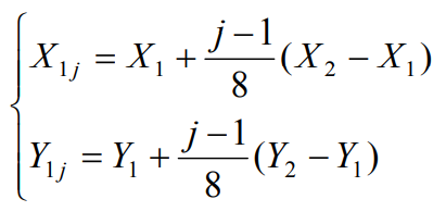
After the four boundary vertices are calculated according to the above formula, the coordinate values of the points on the four boundaries can be deduced according to the corresponding formula. The calculation formula of the coordinate values of the points on the boundary is as follows:
The coordinate value on the tooth top boundary is set as m1j (x1j, y1j), j = 1,2,3 nine
The coordinate value on the tooth root boundary is set as m5j (x5j, y5j), j = 1,2,3 nine

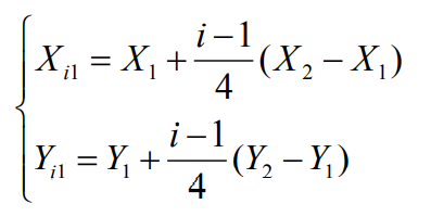
The coordinate value on the small end boundary is set as MI1 (Xi1, Yi1), I = 1,2,3 nine
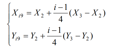
The coordinate value on the big end boundary is set as mi9 (xi9, yi9), I = 1,2,3 nine
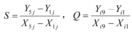
For any point on the grid, the coordinate value of mij (Xij, Yij) is the intersection of two straight lines, and the calculation formula is as follows:
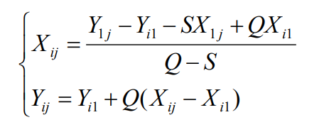
Among them,
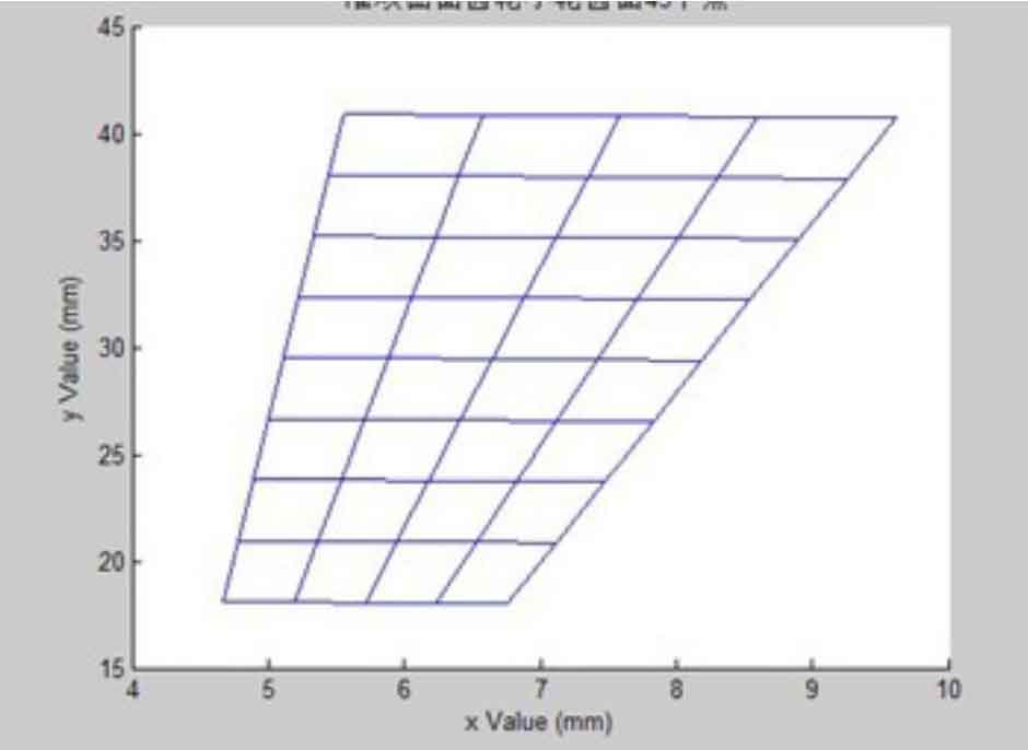
After the above formula is programmed with MATLAB software, the program can be run in MATLAB software to generate plane grid division graphics, as shown in Figure 2. The coordinates of each intersection point in the figure are the plane coordinate points on the tooth surface of hypoid gear.