In order to further understand the spiral bevel gear, this chapter first briefly introduces the classification, basic transmission principle and key geometric elements of spiral bevel gear. Then, the tooth surface generation principle of spherical involute involute spiral bevel gear is analyzed. Finally, based on the generation principle of spherical involute tooth surface, the cutting principle of spiral bevel gear tooth surface is analyzed and studied by using the knowledge of spatial three-dimensional modeling and analytical geometry, which provides a theoretical basis for the research of a new method of spiral bevel gear three-axis linkage milling.
Spiral bevel gear production occupies a very important position in modern machinery manufacturing industry. Because of its characteristics of large coincidence coefficient, stable transmission, strong bearing capacity and high strength, it is widely used in ships, aerospace equipment, national defense technical equipment, machine tools, automobiles, engineering machinery and other mechanical products. In order to further understand the spiral bevel gear, the classification, meshing characteristics and key names and codes of spiral bevel gear are analyzed.
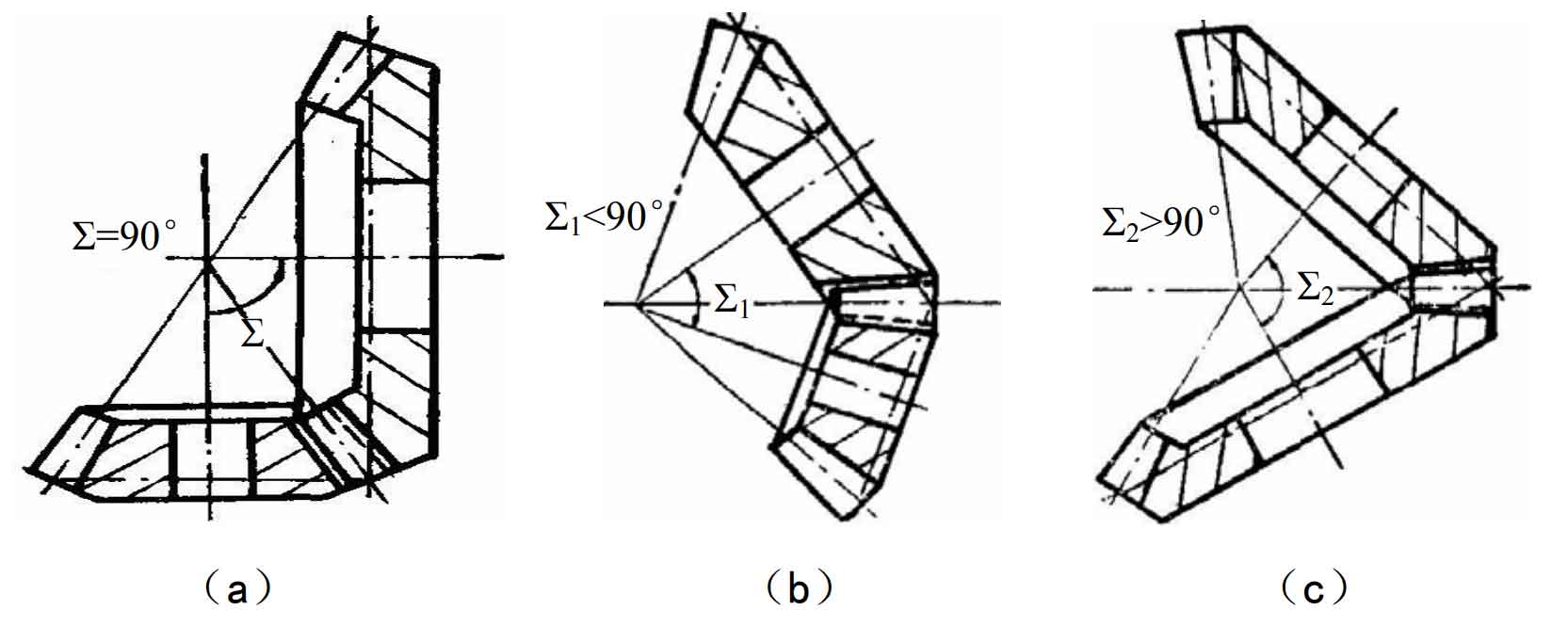
1、 It is classified according to the intersection angle of the spiral bevel gear axis of meshing transmission, which is mainly divided into the following two categories:
(1) the two axes intersect vertically
The axes of meshing spiral bevel gears intersect, and the intersection angle is 90 °, as shown in Figure 1 (a). This kind of bevel gear has no relative slip in the tooth length direction, and is the most widely used in spiral bevel gear transmission.
(2) the axes intersect but are not vertical
When this kind of spiral bevel gears mesh and drive, the axes intersect, and the axis intersection angle can be any angle other than 90 °. One is that the axis intersection angle is less than 90 °, the other is that the axis intersection angle is greater than 90 °, as shown in Figure 1 (b) and (c) respectively. Spiral bevel gears with non vertical shaft intersection angle can only be used in special cases, and are rarely used in mechanical production and manufacturing.
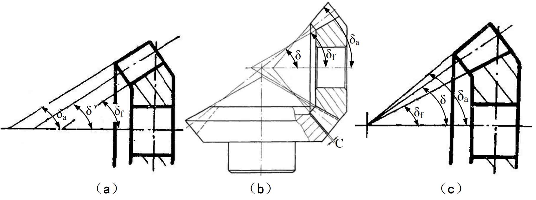
2、 Classified according to the consistency of tooth height, it is mainly divided into the following two categories:
(1) equal height spiral bevel gear
The root cone angle of this kind of spiral bevel gear δ f. Face cone angle δ A and pitch cone angle δ Equal, so that the tooth height from the big end to the small end of the bevel gear is the same, so it is called equal height spiral bevel gear, as shown in Fig. 2 (a). The pressure angle correction of the cutting tool is not necessary for the machining of equal height spiral bevel gear, and the adjustment of the machine tool is relatively simple.
(2) tapered spiral bevel gear
The so-called tapered spiral bevel gear is that the tooth height of the bevel gear gradually decreases from the big end to the small end. According to whether the tooth tip clearance C is consistent, the tapered spiral bevel gear can also be divided into the following two types: one is that the tooth top of one of the bevel gear pairs meshed and transmitted with each other is parallel to the tooth root of the matching bevel gear, and the vertex of the face cone does not coincide with the vertex of the pitch cone, as shown in Fig. 2 (b); The other is that the vertices of the root cone, pitch cone and face cone of the bevel gear coincide with each other, as shown in Fig. 2 (c). Among them, the second kind of spiral bevel gear with shrinkage teeth is more common in practical application.