Because the tooth surface generating line of spherical involute spiral bevel gear is arc-shaped, and the generating line is used as the cutting edge for cutting the tooth surface, the milling cutting edge must ensure that the cutting edge can form an arc-shaped cutting edge line when it rotates at high speed. After the comparison and comprehensive analysis of various blade shapes, it is finally determined to select the cutter with circular edge. When the cutting teeth rotate at high speed, the blade will form a hemispherical surface, as shown in Figure 1. Figure 1 (a) shows the CATIA three-dimensional model of the designed cutter teeth, and its main cutting edge is in the shape of circular arc. In order to facilitate the clamping and disassembly of the cutter teeth and the correction and reuse after the blade is worn, the machine clamp cutter is selected in this paper, as shown in Fig. 1 (b). In the process of bevel gear milling, when the tool rotates at high speed, the spatial motion trajectory of all main cutting edges on the cutter head will form a part of the hemispherical surface.
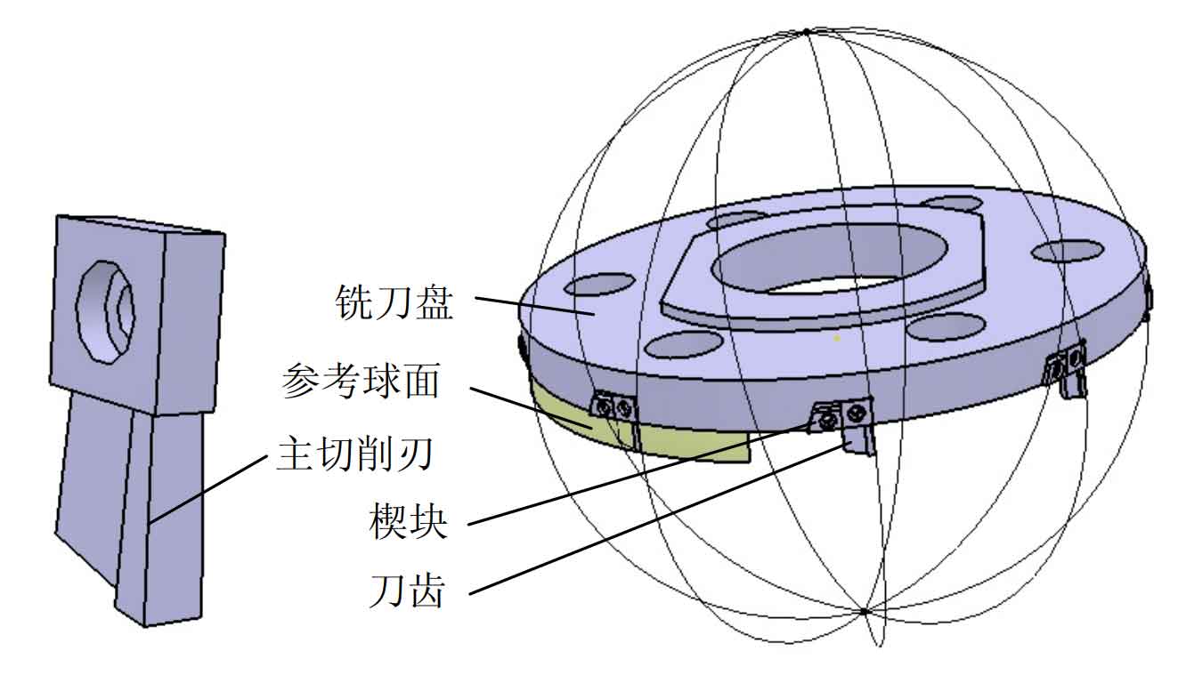
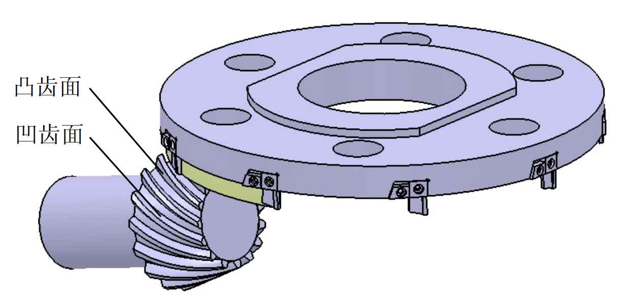
Fig. 1 the main cutting edge of the gear milling cutter is located on the outside of the cutter tooth. It is an external edge milling cutter, which can only process the concave tooth surface of the spiral bevel gear. In order to visually describe the relative relationship between the external edge milling cutter and the spiral bevel gear to be machined in the process of concave tooth surface machining, the three-dimensional model of spiral bevel gear is established by CATIA software, and the schematic diagram of external edge milling cutter machining the concave tooth surface of spiral bevel gear is established by adding constraints in the assembly environment, as shown in Figure 2. If this cutter is used for milling convex tooth surface, it will obviously over cut the solid part of bevel gear teeth. Therefore, in order to process the convex tooth surface of spiral bevel gear, an inner edge milling cutter must also be designed.
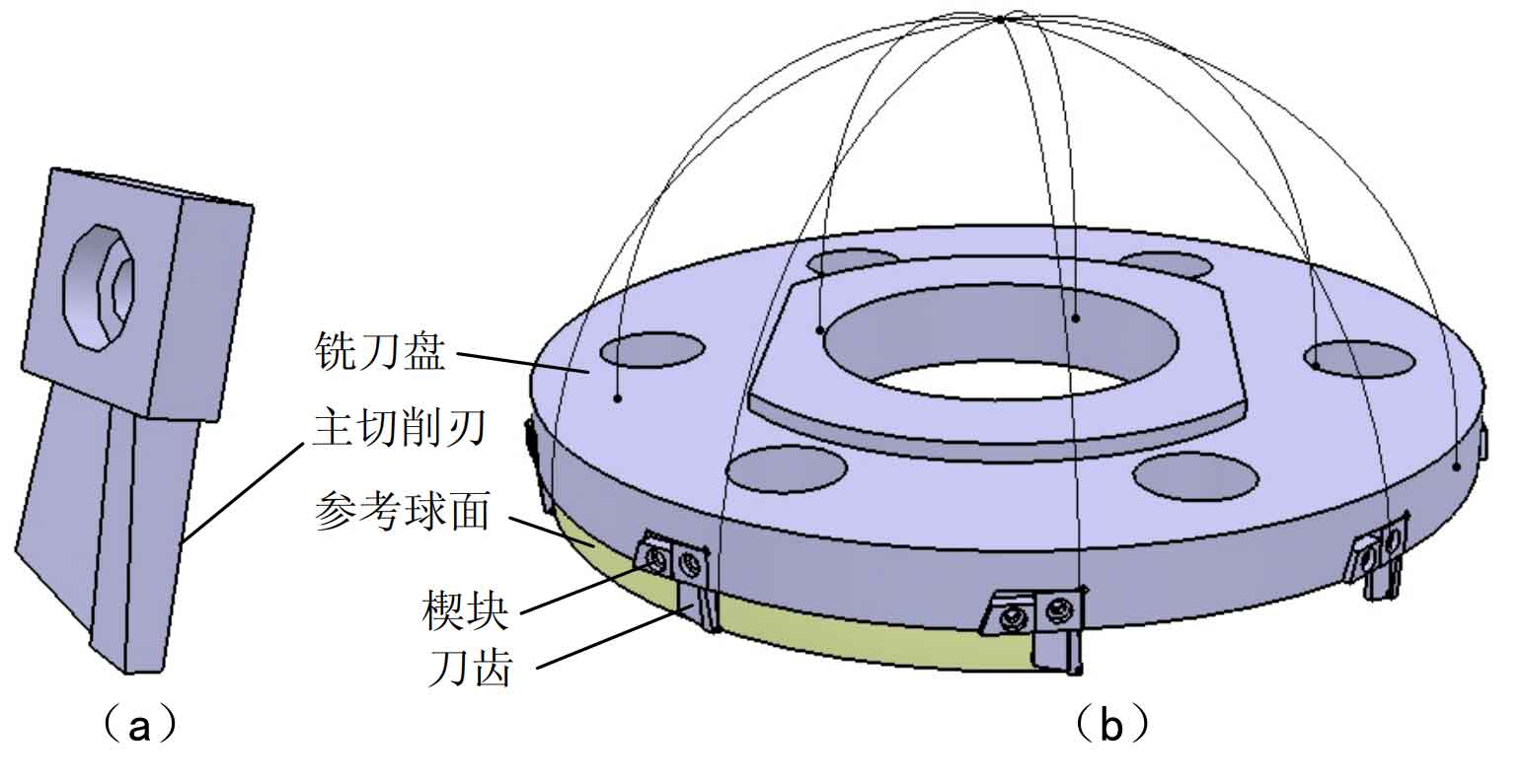
In order to vividly describe the tool required for machining the convex tooth surface of spiral bevel gear – inner edge milling cutter, the three-dimensional model of milling tool is established by CATIA software, as shown in Figure 3. In the process of gear cutting, when the tool rotates at high speed, the spatial motion trajectory of all main cutting edges on the cutter head will form a part of the spherical surface, and all main cutting edges are located on the inner side of the cutter teeth.
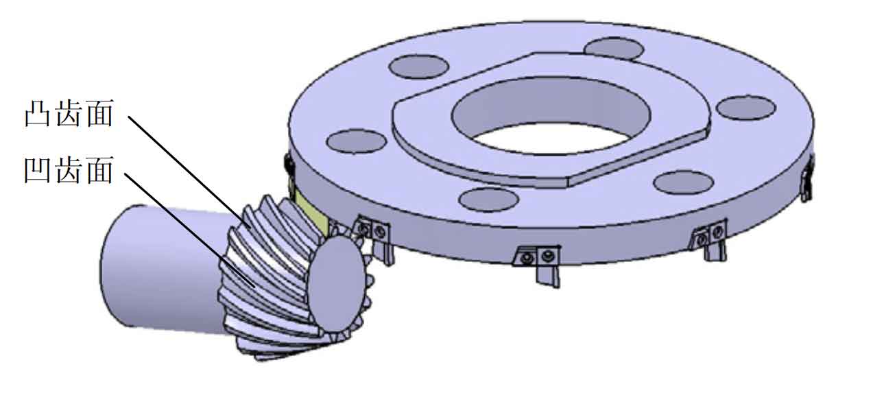
Using this kind of inner edge milling cutter, the convex tooth surface of spiral bevel gear can be milled. Taking the spatial motion track of the main cutting edge when rotating at high speed – the intersection of a part of the hemispherical surface and the (q) plane as the tooth surface generating line, according to the cutting principle of spherical involute tooth surface, it can be seen that the convex tooth surface of spiral bevel gear can be machined only by three-axis linkage, The processing diagram is shown in Figure 4.