
According to the analysis of the cutting motion of the three-axis linkage tooth surface, the machining of the tooth surface of the spherical involute spiral bevel gear can be completed through the movement of the arc-shaped blade along the boundary between the adjustment area and the cutting area, the rotation movement of the blade around its own end point and the rotation movement of the tooth blank. The arc-shaped blade can be regarded as a collection of countless points. The movement of any point on the tooth surface occurrence line in the tooth surface cutting process is along the radial direction shown in Figure 1. Points h and G in Figure 1 are any two points on the occurrence line of the tooth surface of the right-hand spiral bevel gear, which move along the arrow direction in the whole tooth surface processing process. Therefore, the milling of the tooth surface of the spherical involute spiral bevel gear can be realized by the linear movement of the point milling blade along the radial direction of Figure 1 and the rotational movement of the gear blank around its own rotation axis.

Next, the linear motion of any point on the arc generating line of the tooth surface in Figure 1 is analyzed and its motion expression is solved. As shown in Fig. 2, the arc segment AB is the generation line of the tooth surface of the spiral bevel gear, that is, the cutting edge; Point G is any point on the occurrence line; Point o0 is the center of the arc-shaped blade ab. The initial position of tooth surface cutting is defined as: the end point a of the blade coincides with the cone vertex o of the spiral bevel gear, and the straight line segment oo0 is perpendicular to the junction line of the adjustment area and the cutting area. A1B1 in the figure is the initial position of the blade. From the analysis of the three-axis linkage cutting motion of the tooth surface, it can be seen that in the cutting process of the tooth surface, with the cutting edge ω Revolve around point O and ω The speed of 0 rotates around its geometric center o0, and the blade moves from position A1B1 to a3b3. In order to facilitate the analysis, the blade linkage movement is divided into two steps: as shown in Figure 2, ① the blade is first at speed ω Rotate around point O and rotate from position A1B1 to a2b2; ② Then at speed ω 0 rotates around point o0 and rotates from position a2b2 to a3b3. Then point G on the blade rotates from position G1 around point O to G2, and then from position G2 around point o0 to G3. In the actual cutting process, point G moves directly from point G1 to point G3. The above is completed in two steps to facilitate the motion analysis. The final analysis result is not inconsistent with the actual machining process.
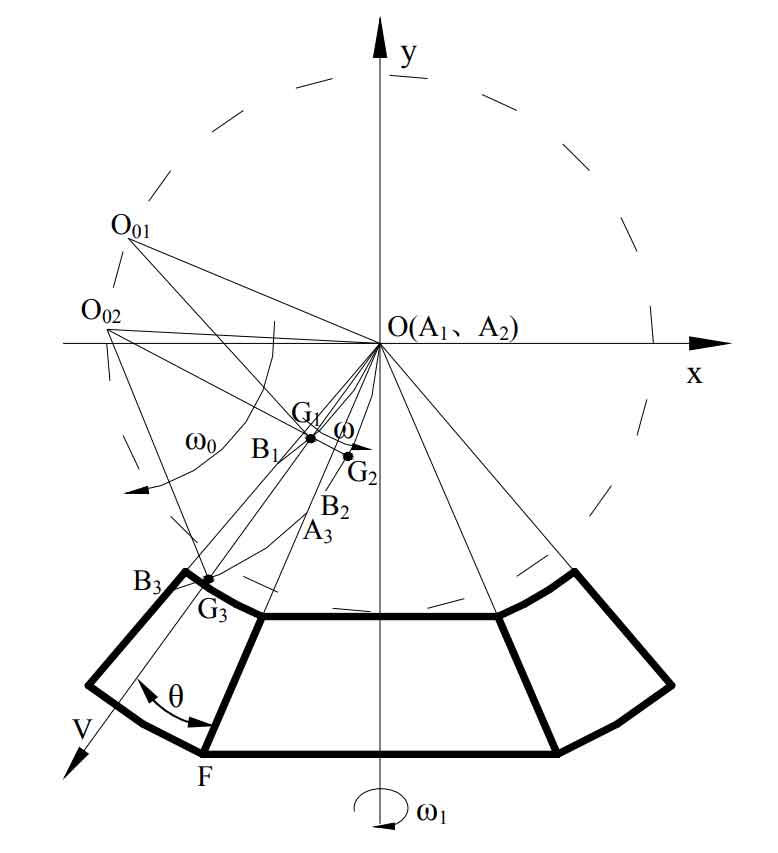
It is assumed that the radial direction at the initial position of point G – the included angle between og1 and the straight line of is θ, Then, since the straight line segment o01a1 is perpendicular to of, the expression of ∠ o01a1g1 can be obtained as follows:
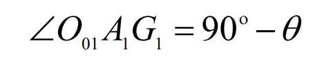
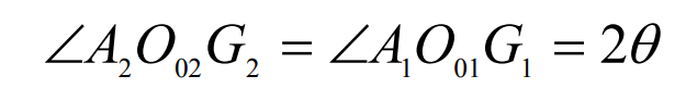
Combining formula and isosceles Δ According to the angle relationship of a1o01g1, the expression of ∠ a1o01g1 can be obtained:

Step 1 of analysis: after time t, point G moves around point o with the arc blade – ab ω When rotating from position G1 to G2, there is an equal relationship between ∠ a1o01g1 and the corresponding angle ∠ a2o02g2, that is:
The second step of analysis: in the same t time, point G moves around point O02 with the arc blade – ab ω When 0 is rotated from position G2 to G3, the angle of ∠ oo02g3 is:

According to the tooth cutting motion analysis of three-axis linkage of spiral bevel gear, ω 0 and ω The relationship must be satisfied: ω 0=2 ω。 By substituting this relation into the formula and simplifying it, another expression of ∠ oo02g3 can be obtained:

Then, after time t, the linear distance between point G and point O is:

Then the moving speed of G-point along the radial direction – og is:
