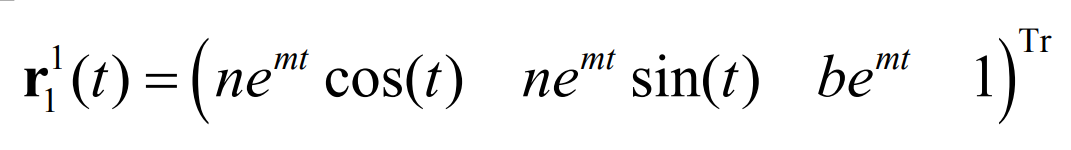
On the cylindrical surface, the equiangular and equidistant helix are unified, that is, the equiangular helix is also the equidistant helix. However, on the conical surface, the equiangular helix and equidistant helix are not unified, and the equiangular helix and equidistant helix have different forms. The conical equiangular helix is characterized in that the included angle of the helix and the straight bus of the conical surface maintain a fixed value, and there is an equiangular helix Γ 1 equation:
The configuration of equiangular conical helix is shown in Figure 1.
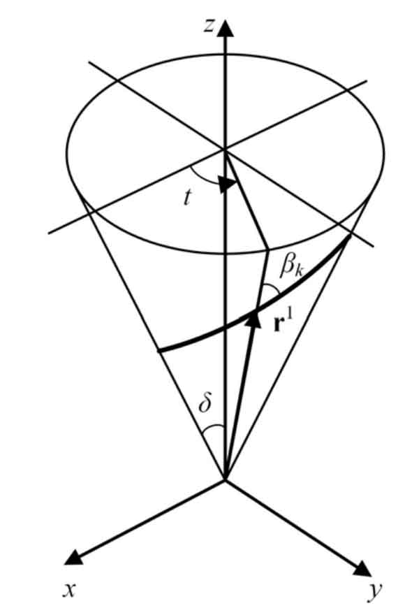
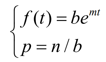
For an equiangular helix, the helix angle β K is a fixed value, and N, m and B are constants that do not change with the curve parameters. According to the comparison formula, for the equal angle helix, there are:
Substitute into the formula to get Γ 2 equation:

Substituting into the formula, we can get:
Substituting into the formula, we can get:
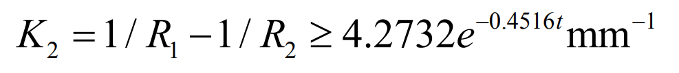
The formula is the conjugate curve equation of pure rolling contact equiangular spiral bevel gear. The formula is the curvature limiting condition of pure rolling contact equiangular spiral bevel gear. These formulas determine the basic design criteria of pure rolling contact equiangular spiral bevel gears. Take a set of design parameters as an example.
In the previous discussion, the section curve Γ S1 and Γ The specific shape of S2 is not limited. Here, the section curve is designed as a double segment arc, as shown in Figure 2. The adoption of this tooth profile is mainly based on the following considerations: the concave arc can increase the thickness of the tooth root, so as to reduce the bending stress; For large and small gears, the cross-section curve can be designed uniformly, which means that the large and small gears can be processed by a tool.
As can be seen from Figure 2:
According to the geometric design parameters of large and small gears, the following formula can be obtained:
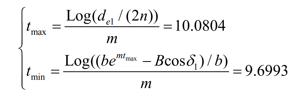
According to the formula, the value range of curve parameter t is:
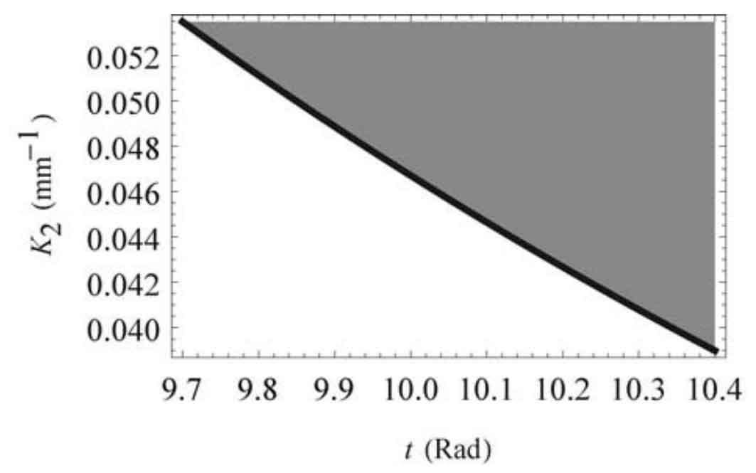
According to the inequality, in order to avoid curvature interference, K2 should be taken in the gray area of Figure 3.
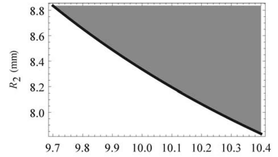
Since inequality (3.64) contains two design quantities R1 and R2, the value of one can be determined first, and the value range of the other design quantity can be obtained according to the inequality. Here, if shilling R1 = 6mm, the value range of R2 is shown in the gray area of Figure 4. Finally, R2 = 9mm.
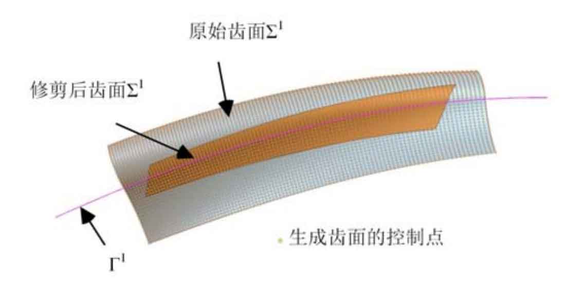
After determining the R1 value and R2, according to the method, the curve can be extended to the tooth surface. Figure 5 shows the 40 × One side tooth surface composed of 100 points. The tooth surface on the other side can also be constructed in the same way. After array, trimming and other operations, Figure 6 shows the final three-dimensional solid model of the equiangular helix pure rolling contact bevel gear.