
Tooth surface loading contact analysis is a very important method to evaluate the contact performance of spiral bevel gear pair. Through tooth surface loading contact analysis, we can comprehensively analyze the influence of various deformations in spiral bevel gear pair on its meshing performance. The finite element method is a computational mechanics method developed in the 1950s. It occupies relatively less computational resources and the results have high accuracy. So far, its calculation theory and application are more mature than other computational mechanics methods, such as finite difference method, boundary element method, meshless method, multigrid method and so on. Therefore, in engineering practice, the finite element method is widely used to evaluate the performance of new equipment. In the design and calculation of spiral bevel gear, compared with the traditional analysis method of spiral bevel gear pair based on Hertz theory, the finite element method has higher accuracy, more data can be obtained, the problem processing is more standardized and easy to be popularized. Therefore, the general finite element method is gradually introduced into the mechanical analysis and design of spiral bevel gear pair. In this paper, the finite element method is also used to analyze the tooth loading contact of pure rolling contact equiangular spiral bevel gear.
The finite element method is a computational mechanics method developed from the theory of elasticity. Its mechanical basis is the virtual displacement principle, and its mathematical basis is Hu Haichang jiujinjiuichiro’s generalized variational principle and weighted residual method (the two methods can be deduced from each other mathematically). Although the finite element method was originally developed from the mechanical theory, it has become a mature numerical method for solving partial differential equations after many years of improvement. Theoretically, any problem that can be described by partial differential equation can be solved by finite element method. Due to the limitation of space, this paper only briefly introduces the general process of solving elastic equations by finite element method.
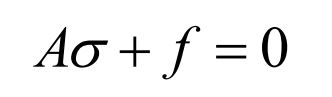
The equilibrium differential equation of elasticity is:
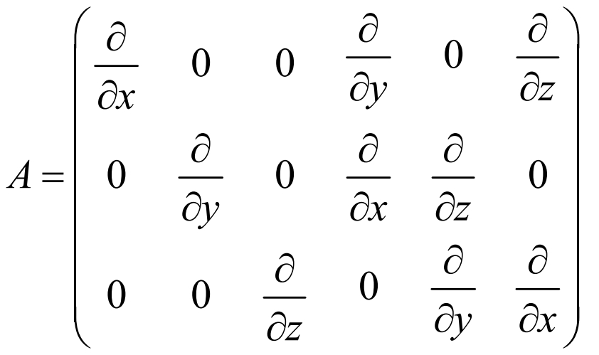
A is the differential operator:
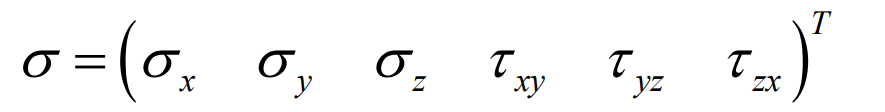
σ Is the stress array:
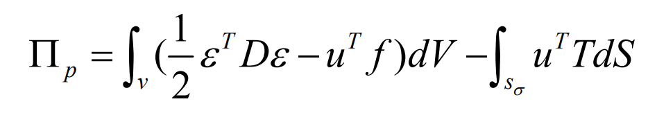
According to the principle of minimum potential energy of elastic structure, the differential equation is equivalent to finding the minimum value of formula functional.
At this time, it can be seen that even according to the principle of minimum potential energy, solving the stress or strain distribution of complex model is still a difficult integral problem. Therefore, the finite element discretization method is used to approximate the complex model with piecewise simple model. However, generally speaking, the stability of numerical integration is higher than that of numerical differentiation. Therefore, by using the variational principle, the solution of differential equation can be transformed into the solution of integral equation, and the original partial differential equation can be solved efficiently by computer.
In the finite element method, the approximate value of the unknown quantity can be obtained through the piecewise function. After dividing the continuum into multiple elements, it is considered that the displacement distribution function in each element is a linear combination of approximate functions, and the displacement is transmitted between elements through nodes. In order to get the correct solution, the approximate function of any element can not be taken arbitrarily and needs to meet the normalization condition, which leads to the selection of approximate function is usually related to the element shape, so it is also called shape function. The displacement function in each element is obtained by linear combination of shape function and undetermined parameters, which can be expressed by node displacement. The unknown function composed of the undetermined parameters represented by the node displacement and the shape function of each element is substituted into the functional minimum value expression. After numerical integration, it finally becomes a linear equation system for solving the node displacement. Its form is generally as follows:
K is the structural stiffness matrix, which consists of the stiffness matrix of each element. It only depends on the shape function and physical parameters. A is the displacement array of each node, and P is the structural load array. In this way, solving complex partial differential equations eventually becomes solving simple algebraic equations.
Recently, the general finite element software has developed a new type of surface to surface contact element. The use of surface to surface contact element for contact analysis does not need the node alignment of the contact area, so it greatly simplifies the establishment of finite element analysis model and improves the work efficiency. The state of the contact system is uniquely determined by the geometric boundary conditions and the non embedded conditions on the contact boundary.