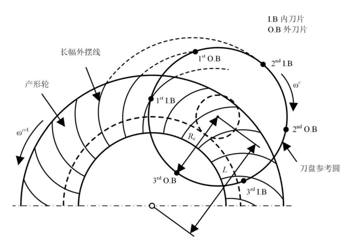
Long epicycloid bevel gear refers to the bevel gear whose tooth line is a long epicycloid. In the current industrial application, Klinger bevel gear and Oricon bevel gear are long epicycloid bevel gears. The long epicycloid bevel gear is usually processed by the continuous indexing method with the plane generating wheel, and the tooth line of the generating wheel is a long epicycloid. The tooth surface of long epicycloid bevel gear is mainly generated by generating method. In generating the generating motion of the tooth surface, two main motions are set. The first motion is the continuous indexing motion. In this motion process, the long epicycloid tooth profile generating wheel is generated, as shown in Figure 1. This profile wheel can be regarded as the mating gear of the machined bevel gear. In the continuous indexing motion, there is the following motion relationship between the tool and the shaking table:
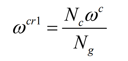
here, ω CR1 represents the angular velocity component of the shaking table in continuous indexing motion, ω C represents the tool angular speed, NC represents the number of tool edge groups, and ng represents the number of profile teeth.
The second motion is to generate the generating motion of the small wheel of the long epicycloid bevel gear or the large wheel of the long epicycloid bevel gear. In this movement process, the pinion or big gear is processed through the envelope movement of the shaping wheel. At this time, there is the following motion relationship between the processed long epicycloid bevel gear and the shaking table:
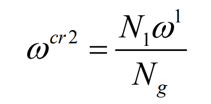
here, ω CR2 represents the angular velocity component of the shaking table in the spreading motion, ω 1 represents the angular velocity of the processed long epicycloid bevel gear, and N1 represents the number of teeth of the processed long epicycloid bevel gear.
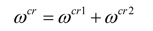
Finally, the angular velocity of the shaking table is formed by the superposition of two motions of the formula, namely:
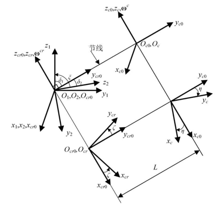
According to the above analysis of the machining motion of long epicycloid bevel gear, the motion coordinate system suitable for the analysis of long epicycloid bevel gear can be constructed. The motion coordinate system is shown in Figure 2.
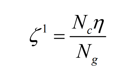
From the formula, we can get:
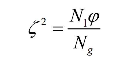
From the formula, we can get:
When the production wheel, pinion and big gear have the same pitch line with each other, and the contact point only moves along the pitch line, the production wheel, pinion and big gear naturally have pure rolling contact with each other. According to this idea, it is discussed under what circumstances the forming wheel, pinion and big gear have the same pitch line with each other.
In the coordinate system S0, the points on the pitch line of pinion and gear can be expressed by the following equation:
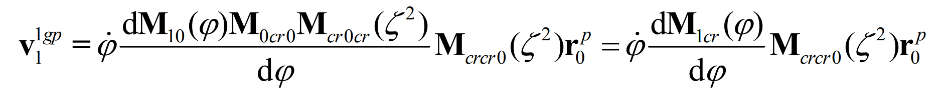
Then, in the shaping movement, at this point, the relative speed of the shaping wheel and the pinion is:
here, φ. express φ Time derivative of.
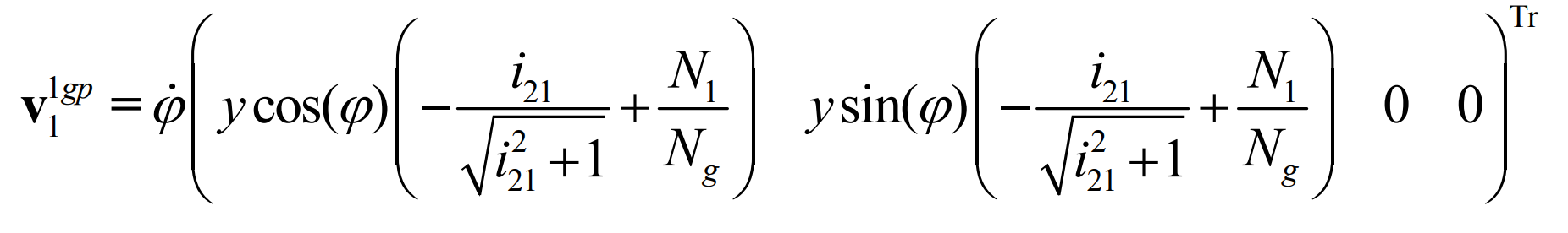
Substituting the formula, the relative motion speed can be calculated as follows:
In order to ensure that the profile wheel, pinion and big gear have the same pitch line with each other, there shall be:
The formula is:
Therefore, when the number of teeth of the production wheel and pinion is as shown in (3.84), the production wheel, pinion and pinion have the same pitch line. At this time, the continuous pure rolling contact long epicycloid bevel gear model can be obtained by making the contact point move only along the common pitch.
Select the intersection of the blade and the pitch plane as the starting point P to generate a curve Γ g. The potential vector of this point can be expressed by the following equation:
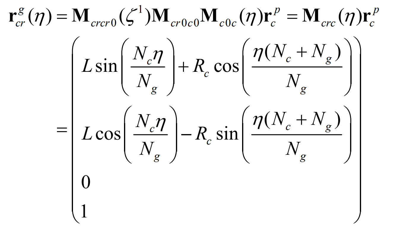
In the continuous indexing motion, the trajectory of P in the coordinate system scr0 forms a long epicycloid, Γ g。 Γ The equation of G can be obtained by the coordinate transformation from SC to SCR:
According to the space conjugate curve theory, in the generative motion, Γ G can generate a spatial conjugate curve in the coordinate system of the small gear of the long epicycloid bevel gear Γ 1. Generate a spatial conjugate curve in the large gear coordinate system of long epicycloid bevel gear Γ 2。 In the unfolding movement, Γ The trajectory of G in S1 can be obtained by the coordinate transformation from SCR to S1:

The relative motion between the production wheel and the pinion can be obtained by the following formula:
To guarantee Γ G and Γ 1 is pure rolling contact, and the relative motion speed must be equal to 0, that is:
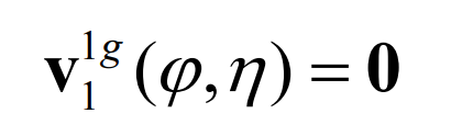
Thus, from the formula, there are:
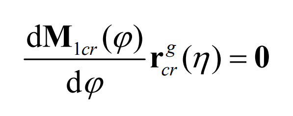
According to the formula and the theory of spatial conjugate curve, the meshing equation can be obtained:
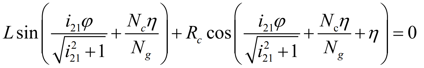
Thus, from the formula, we can get Γ The equation of 1 is:
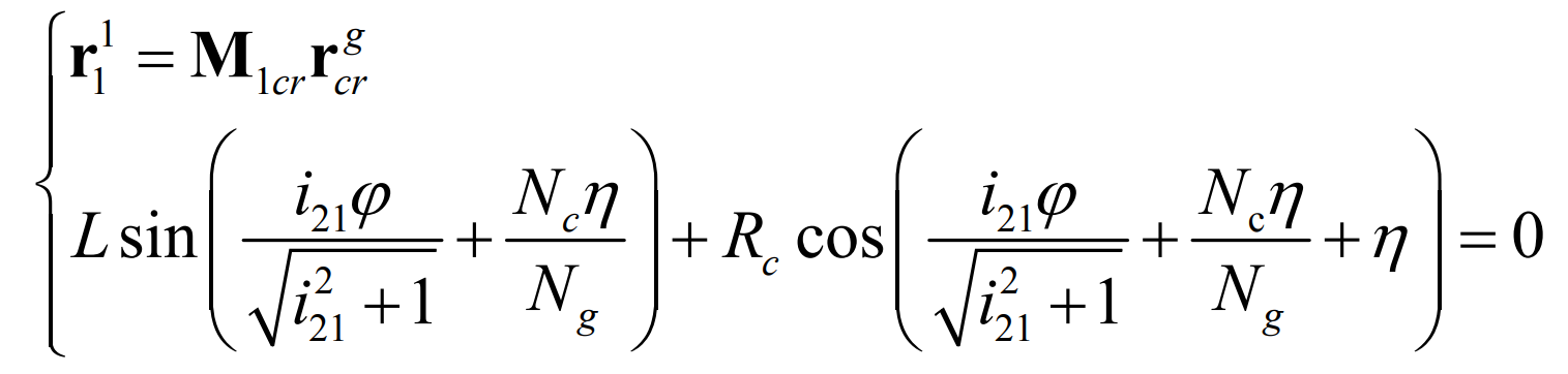
Similarly, it can be obtained Γ The equation of 2 is:
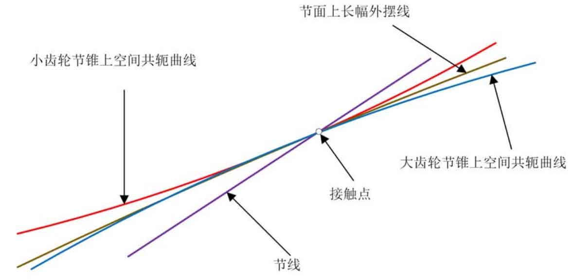
As can be seen from the formula, in the derivation Γ 1 and Γ 2, the meshing equation is consistent, which means that in the evolution motion, Γ G and Γ 1. And Γ G and Γ 2 has the same contact point, and at this contact point, pure roll contact exists. At this point of contact, Γ g, Γ 1 and Γ 2 has a common normal N1. In fact, the normal direction is the main normal direction of the blade line at this point. Considering the production wheel, the pinion and the big gear have the same pitch line, and the relative speed of the pinion and the big gear is zero at the contact point, as shown in Figure 3. Therefore, the meshing equation n1v12 = 0 is naturally satisfied for the large and small gears of the processed long epicycloid bevel gear. Therefore, according to the meshing theory, the processed large and small gears are in pure rolling contact and can mesh correctly.