
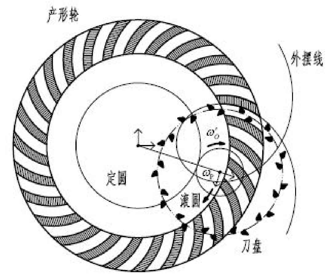
The forming process of bevel gear face hobbing can be regarded as a meshing transmission between the generating wheel and the processed gear. The relative position and relative motion of the generating wheel and the processed gear completely determine the tooth surface shape of the gear. Due to the use of continuous indexing machining, the motion of this kind of machine tool is more complex than that of arc bevel gear milling machine. Therefore, to study the motion control of end face hobbing machining of full CNC bevel gear milling machine, it is necessary to analyze the relative motion relationship among cutter head, shaking table, workpiece and production wheel in the basic machine tool model of end face hobbing machining, and clarify the principle of continuous tooth division of end face hobbing machining. When the spiral bevel gear end face hobbing is processed, the rotary motion of the milling cutter head and the rotary motion of the workpiece cooperate with each other according to a certain transmission ratio, so that the spiral bevel gear is continuously indexed in the processing process. At the same time, the cutter teeth of the milling cutter head form the tooth line shape of a long epicycloid on the forming wheel. It can be seen that during the machining of Cycloid Bevel gear, the profile tooth shape is the rolling circle represented by the cutter head. When pure rolling is made on the fixed circle represented by the profile wheel, it is formed by the track of the blade, and the engagement between the profile wheel and the workpiece develops the workpiece tooth shape, as shown in the figure.
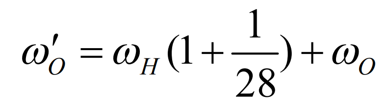
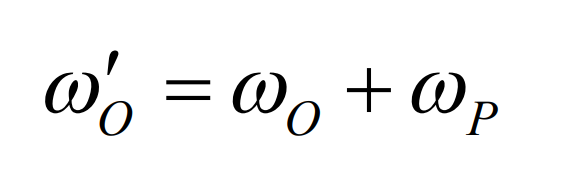
The synthetic speed of bevel gear calculated from this is the same as that obtained by analyzing the transmission chain of mechanical gear milling machine. The motion of the additional cutter head just corresponds to that of the additional cutter head 1. This shows that for different types of machining machines, when calculating the synthetic speed of the workpiece, the difference between the absolute speed of the cutterhead and the theoretical speed shown in equation 2 should be compared, and it should be compensated according to the number of teeth between the cutterhead and the workpiece.