
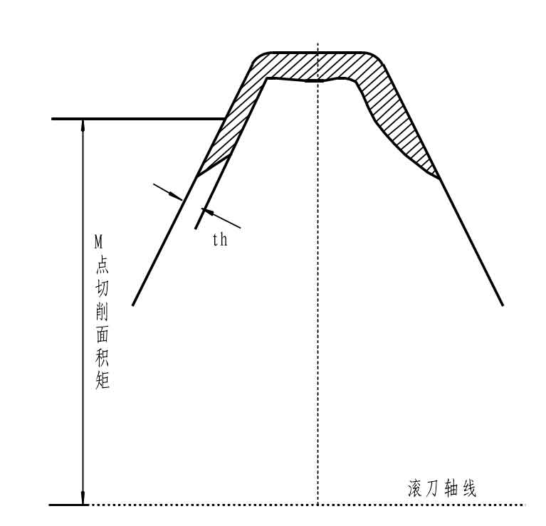
Theoretically, the larger the rake angle of the gear hobbing hob, the smaller the cutting load of the cutter teeth. However, it is difficult to ensure the accuracy of the tooth profile in the manufacturing process, and chip clamping and cutting are easy to occur in use. Now, due to the improvement of the manufacturing technology of the gear hobbing hob, the advanced and high-efficiency gear hobbing hob adopts multi groove, multi head and high speed cutting, and the single tooth of the gear hobbing hob bears very little force, Now the common practice is to design the front angle of the gear hobbing hob to zero degrees, and the rear angle is formed by the shovel teeth. After the gear hobbing hob is blunt, it needs to be sharpened again. Therefore, the shape of the side relief surface of the gear hobbing hob should conform to the meshing nature of the hob. The principle of gear hobbing hob is shown in the figure.
The relationship between the designed back angle of the top edge of the gear hobbing hob and the radial back clearance K is as follows:
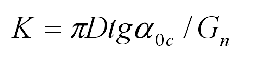
Where:
D — outer diameter of gear hob;
GN — number of chip holding grooves of gear hobbing hob;
α 0C — back angle of top edge of gear hob.
When manufacturing the gear hobbing hob, the radial relief K value of the gear hobbing hob is generally determined under the condition of ensuring that the designed back angle of the top edge is 10 ° ~ 12 °. After the K value is rounded (the calculation accuracy is guaranteed to 0.5mm), the designed back angle of the side edge is verified. Generally, the designed back angle of the side edge shall not be less than 3 °, otherwise it is not conducive to chip removal. The relationship between the designed back angle of the side edge and the amount of shovel back is as follows:
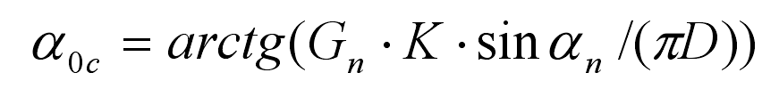
Where:
α N — normal tooth profile angle of indexing circle of gear hobbing hob;
α 0C — designed back angle of side edge of gear hobbing hob.