
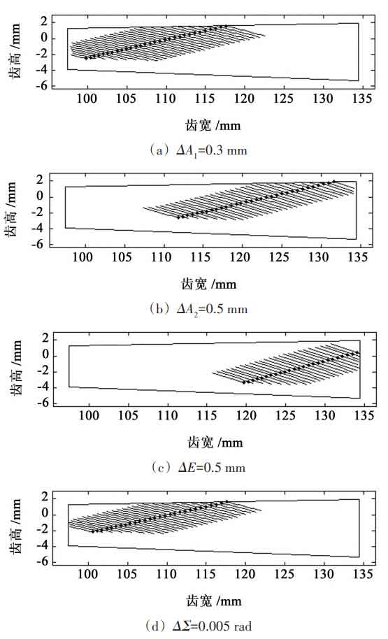
According to the relevant provisions of GB / T 11365-2019 standard, the specific accuracy values of spiral bevel gears and hypoid gears can be determined. Among them, four installation errors are specified, and the shaft intersection angle deviation is taken respectively ΔΣ Is 0 005 rad. Shaft spacing deviation Δ E is 0 5 mm. Axial displacement of small wheel Δ A1 is 0 3 mm and large axle displacement Δ A2 is 0 5 mm, analyze the sensitivity of tooth surface impression to installation error. Fig. 1 (a) to Fig. 1 (d) show the influence of various installation errors on the tooth surface impression under the inner diagonal design. When there is installation error, the tooth surface impression will move to the small end or large end, and the inner diagonal design is easy to have edge contact at the tooth top or root; Especially when moving to the small end, the tooth height of the small end of the tapered spiral bevel gear gradually decreases, making it more prone to edge contact. The sensitivity of each single error is that the axial displacement of the large wheel shaft is roughly the same as that of the small wheel, the deviation of the shaft spacing is greater than the axial displacement, and the deviation of the shaft intersection angle is the most sensitive.
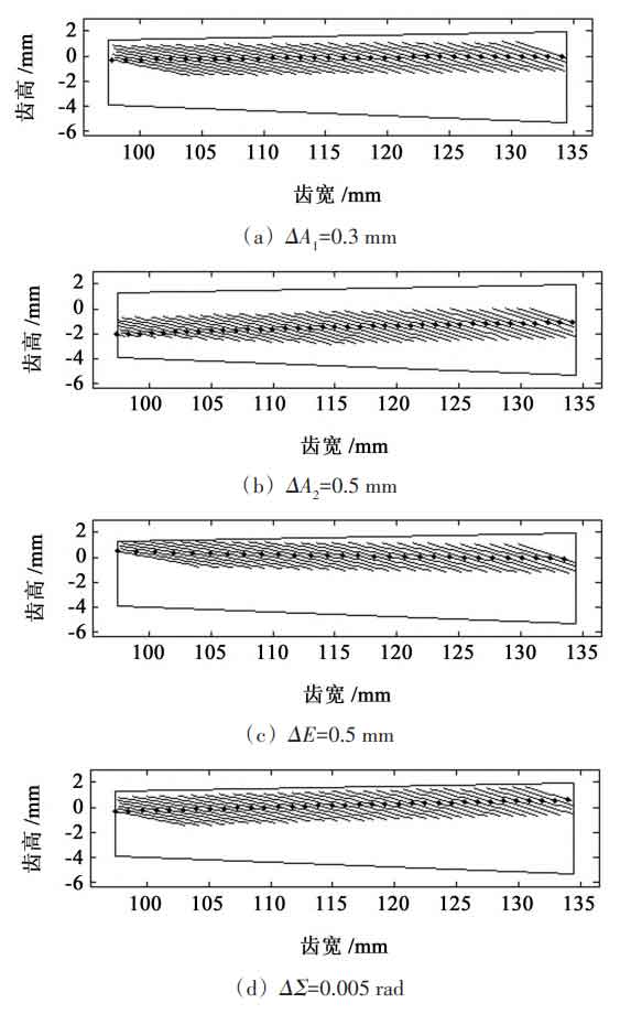
Take the same installation error value, and the tooth surface impression designed along the tooth length is shown in Fig. 2 (a) ~ Fig. 2 (d). It can be seen that the design is not sensitive to the axial displacement of the small wheel and the axial displacement of the large axle, and the tooth surface impression moves up and down, but is more sensitive to the shaft spacing deviation. This is because the tooth surface impression moves along the tooth length direction, and the shaft spacing deviation acts on the movement of the tooth surface impression almost according to the relationship of 1 ∶ 1; The deviation of the axial intersection angle will make the impression on the tooth surface inclined to a certain extent. By analyzing its sensitivity, it can be seen that the axial displacement of the large wheel axle is roughly the same as that of the small wheel, followed by the axle intersection angle deviation, and the most sensitive is the axle spacing deviation. Therefore, the design of contact path along the tooth length can reduce the error sensitivity of spiral bevel gear.
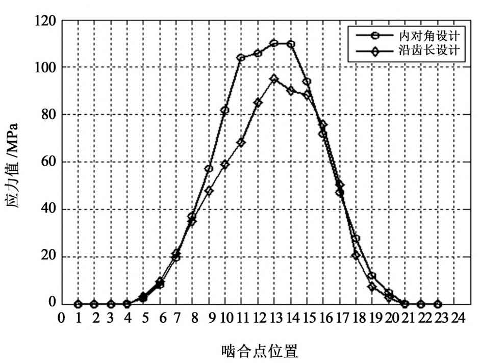
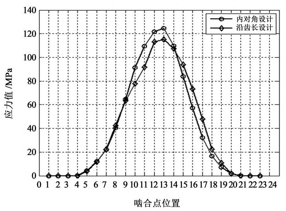
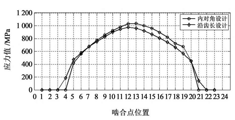
With the help of spiral bevel gear tooth load contact analysis (LTCA) technology, when the load torque of the large wheel is 1000 n · m, the tooth root bending strength and tooth surface contact strength under two kinds of large coincidence design are analyzed, and the results are shown in Fig. 3. It can be seen from Figure 3 (a) that the maximum tensile stress of the small wheel tooth root designed in the inner diagonal is 110 236.7 MPa. According to Fig. 3 (b) ~ Fig. 3 (c), the maximum tensile stress value of large wheel tooth root can reach 127.5 MPa 703 4 MPa, and the maximum contact stress value of the tooth surface is 1033 386 7 MPa; Therefore, it can be concluded that the maximum tensile stress value of the small wheel tooth root designed along the tooth length is 95 238.7mpa, the maximum tensile stress value of the gear root of the big wheel is 114.7mpa 864.2 MPa, the maximum contact stress on the tooth surface is 973.5 MPa 738 5 MPa。 Fig. 4 shows the load transmission errors of two kinds of large coincidence design. The load transmission error amplitudes of inner diagonal design and along tooth length design are – 13 respectively 53 “and – 9 292″。