
The dual frequency induction electromagnetic thermal coupling mode of bevel gear is analyzed, and the mode of alternating medium and high frequency current is determined to realize dual frequency induction heating, that is, dual frequency induction heating in medium and high frequency sections. The problem of cycle times is involved in the process of alternately applying medium and high frequency current. It can be realized by simply alternating medium and high frequency current once to realize dual frequency induction heating, or by alternately applying medium and high frequency current for many times. The dual frequency induction heating process is not a simple linear superposition of two single frequency induction heating processes. The permeability and other parameters that determine the heat generation rate are different under different temperature models. While ensuring the same heating time of medium and high frequency, changing the number of cycles will lead to different temperature rise processes, and different temperature rise processes will lead to different temperature distribution.
On the premise that the total time of medium and high frequency induction heating is the same and the proportion of medium and high frequency induction heating time in each cycle is unchanged, the application times of medium and high frequency are analyzed, as shown in Figure 1.
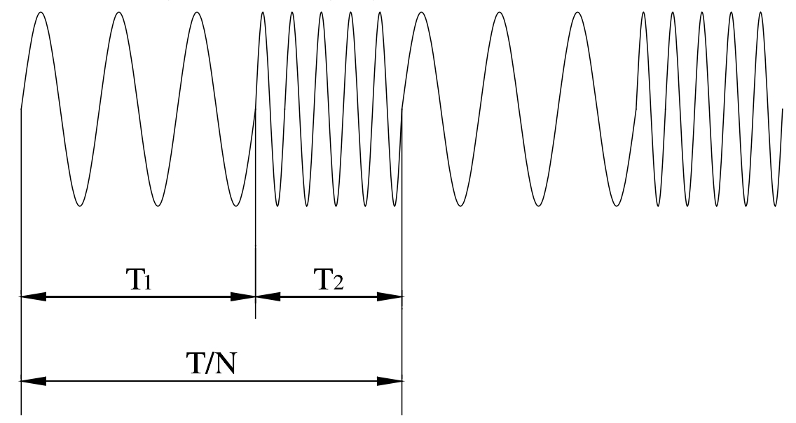
In Figure 1, t is the total induction heating time, each high-frequency induction heating time is T1, each medium frequency induction heating time is T2, and the number of medium and high-frequency cycles is n. then the relationship between the number of medium and high-frequency induction heating cycles and the medium and high-frequency induction heating time in each cycle is: T / N = T1 + T2.
L2 point is selected to analyze the time history of temperature rise in the process of dual frequency induction heating. The temperature rise curve of dual frequency induction heating of bevel gear when the number of medium and high frequency cycles is 8 and the number of cycles is 2 is shown in Figure 2a). Compared with the two curves in Figure 2a), it can be seen that the temperature rise law of the two curves is almost the same, the temperature values fluctuate and rise, and the number of wave peaks is the same as the number of cycles. At about 16S, the peaks of the two curves become smaller obviously, and the rising trend of temperature value slows down obviously. This is because the L2 temperature at this point reaches the “Curie point” temperature, and the material loses magnetism. At this time, the permeability of the bevel gear material decreases to close to 1, resulting in a significant reduction in the rate of temperature rise. Because the medium frequency current is applied first and then the high frequency current is applied, the efficiency of medium frequency induction heating is lower than that of high frequency induction heating. During the rising process of the curve, the temperature value of point L2 maintains an upward trend in the process of high-frequency induction heating. Before the temperature value reaches the “Curie point”, the increase is large, and the increase decreases with the increase of time. It is also due to the gradual decrease of the permeability of the material and the decrease of induction heating efficiency with the increase of temperature. In the process of medium frequency induction heating, in addition to the initial time, the temperature rises in the process of medium frequency induction heating, and the later temperature value is almost always in the process of decline. From the decrease of temperature value, it can be seen that the efficiency of medium frequency induction heating is significantly lower than that of high frequency induction heating. In the process of medium frequency induction heating, the temperature value generally decreases first and then increases. The decrease of temperature value is due to the lower heat generation than loss of medium frequency induction heating at point L2. Moreover, high frequency induction heating will produce high local temperature, and the heat conduction velocity is related to the temperature difference, so the excessive temperature difference accelerates the decrease of temperature difference in the process of medium frequency induction heating.
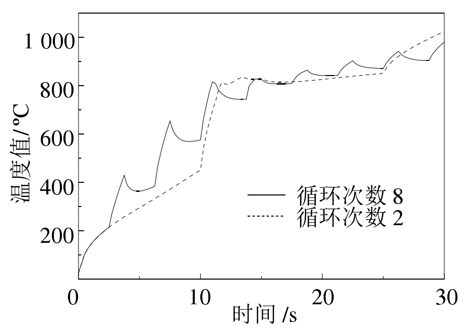
Comparing the two curves in Figure 2a), it can be seen that the rising laws of the two curves are almost the same. In the rising process, the two curves intersect many times, that is, at this time, the temperature values of the two curves are the same. At 30s, there is a difference between the temperature values of the two curves. The temperature of point L2 when the number of cycles is 8 is lower than that when the number of cycles is 2, indicating that when the total time of dual frequency induction heating is fixed, increasing the number of cycles can help to avoid excessive local temperature. However, in practice, the number of electrical switching of medium and high frequency power supply is limited. This should be considered in numerical simulation. The minimum value of each medium and high frequency induction heating time should not be too small. On the other hand, comparing the two curves in Fig. 2a), it can also be seen that the maximum value of the temperature difference between the two curves also decreases gradually with the increase of time. After reaching the “Curie point” temperature value, the temperature difference decreases significantly.
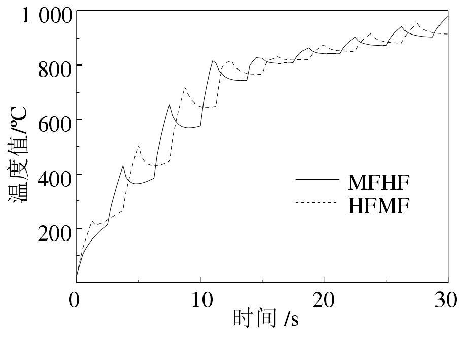
Fig. 2b) is the temperature rise curve of L2 at the time point when the sequence of medium and high frequency induction heating is changed. HFMF (HF: high frequency; MF: medium frequency) indicates that high frequency induction heating is carried out first, followed by medium frequency induction heating, and mfhf indicates that medium frequency induction heating is carried out first, followed by high frequency induction heating. Comparing the two curves in Fig. 2b), it can be seen that the peak value of the temperature difference between the two curves is large before reaching the “Curie point” temperature, and the temperature difference between the two curves is small after reaching the “Curie point” temperature. According to the above analysis, when the induction heating time is long enough and the surface temperature of bevel gear reaches the “Curie point”, changing the sequence of medium and high frequency induction heating has little effect on the final temperature field model of dual frequency induction heating.
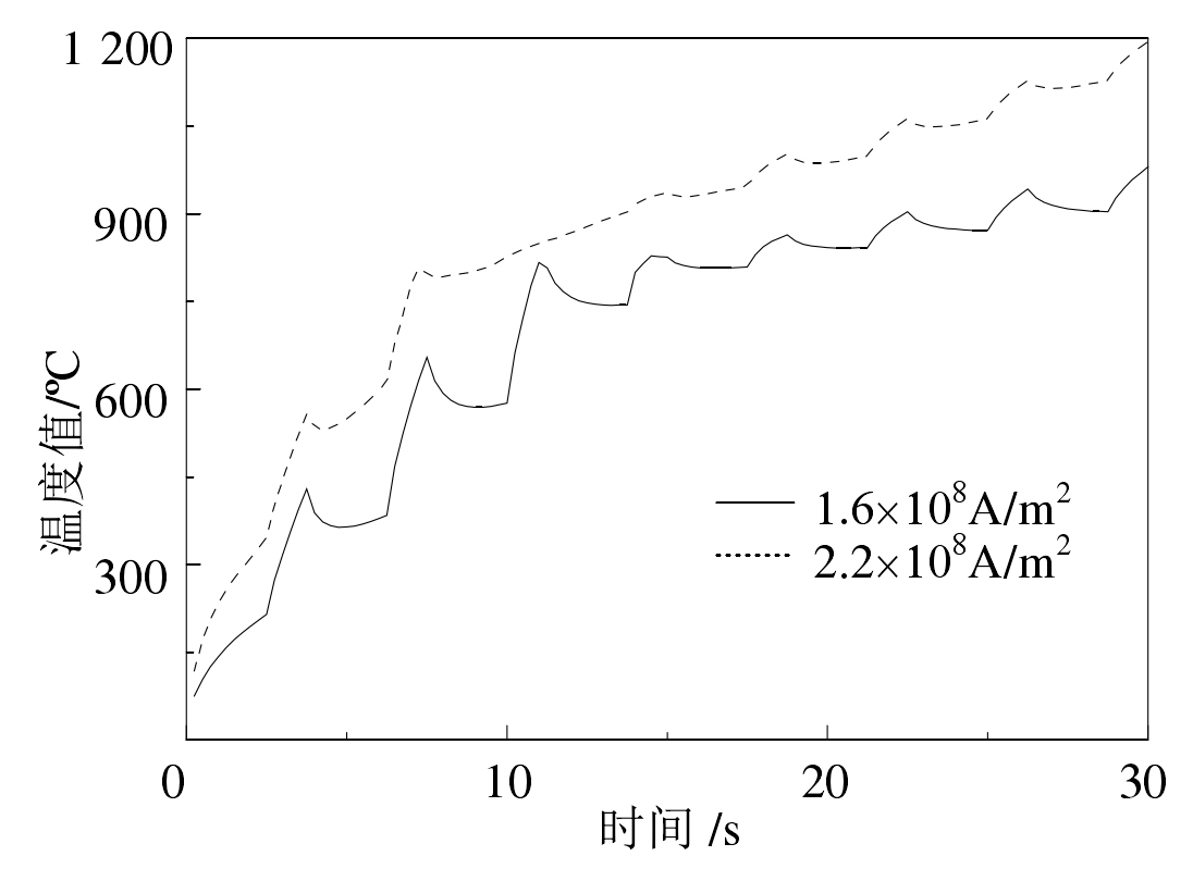
It can be seen from Fig. 2a) that the temperature decreases significantly during the medium frequency induction heating process, mainly because the efficiency of medium frequency induction heating is significantly lower than that of high frequency heating. The efficiency of intermediate frequency induction heating can be improved by increasing the current density of intermediate frequency induction heating. As can be seen from figure 2C), when the current density of intermediate frequency induction heating is increased from 1.6x10⁸a/m2 to 2.2x10⁸a/m2, the temperature rise speed of point L2 is significantly increased, and the efficiency of dual frequency induction heating is significantly improved. In the process of segmented dual frequency induction heating, In the process of medium frequency induction heating, the temperature drop decreases significantly.