
In the helical gear transmission of hybrid electric vehicle, although the rolling motion conditions are considered in the tooth surface design, and the rotational angular velocity of the two helical gears is constant, there is vibration excitation for each pair of helical gears, especially in the compound planetary gear mechanism, multiple pairs of helical gears mesh at the same time, which becomes a multi degree of freedom nonlinear system with more complex vibration excitation and transmits the tooth force of torque in the transmission system, It will inevitably deform the meshing gear teeth. Even if the gear tooth power excited by the specified constant torque is far greater than the static force transmitted by itself.
The causes of internal excitation include the change of meshing stiffness K (T), the rolling of tooth surface and the alternation between single tooth and double tooth meshing. Not only the meshing defect, but also the perfect transmission system will cause vibration excitation when it deviates from the ideal meshing conditions, pitch deviation and rotation deviation. The periodic variation of meshing stiffness can be described by the mean value km, Fourier coefficient KC and meshing frequency FZ as follows:
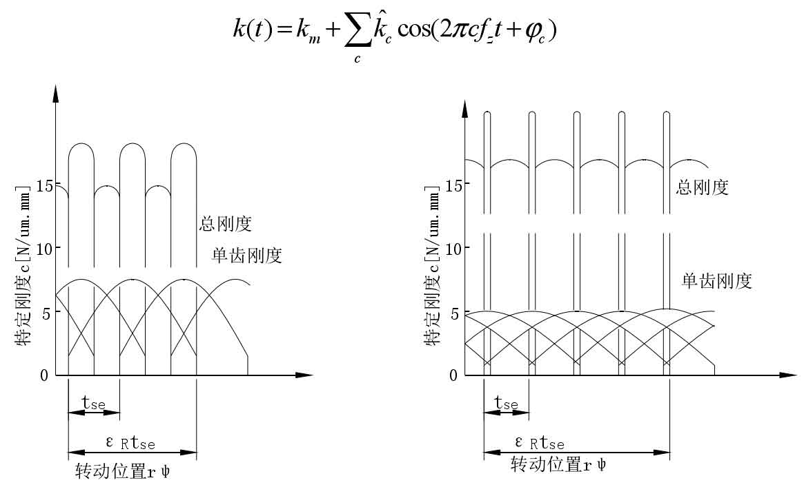
In the transmission system, the torsional stiffness of helical gear can be calculated with the help of numerical calculation method, but due to overlap, according to the different position of helical gear and the different number of teeth in meshing state, the effective stiffness of helical gear changes continuously in a meshing cycle. As shown in Figure 1, the stiffness change curve of helical gear pair obtained when the coincidence degree is different. From the figure, we can see the relationship between the total stiffness and the meshing stiffness of single tooth, For spur gears, two pairs of teeth are meshed at the same time in the double tooth meshing area. The step mutation of the meshing comprehensive stiffness of helical gears is significant, and there is a large jump when the coincidence degree changes. For helical cylindrical gears, there is not only single tooth elastic deformation, but more teeth of helical gears are in meshing. Therefore, although the meshing comprehensive stiffness of helical gears is time-varying like that of spur gears, But the jumping of stiffness is relatively small. Therefore, a few Fourier numbers are sufficient to describe it.
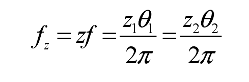
In two helical gears (shaft 1: angular speed θ 1. Number of teeth Z1; Axis 2: angular velocity θ 2. Number of teeth Z2) relationship between meshing point, meshing frequency and speed and number of teeth:
Helical gear elements support a method to determine the effective meshing stiffness. This method is similar to a single specific tooth stiffness K ln = 14 [n / um. Mm]. The specified stiffness is related to the tooth width BW and transverse direction, so the tooth meshing stiffness kBT [n / M] can be calculated. For helical gears, there are more teeth in meshing state, so the number of meshing teeth is determined by the coincidence degree εγ express:
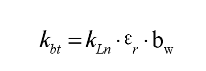
Kbt is the stiffness in the normal direction of the helical gear end face, β B is the helix angle of the base circle, from which the meshing stiffness in the normal direction can be calculated:
In the process of meshing, the meshing stiffness KF of helical gear changes with different meshing positions and is related to the number of teeth actually involved in meshing. Its calculation formula is:
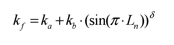
Where ln is the engagement length:
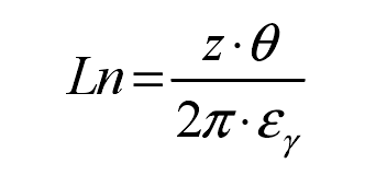
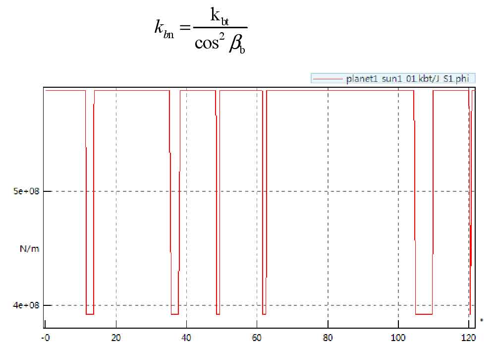
Here Ka is the static stiffness, KB is the dynamic stiffness, and Z is the number of teeth involved in meshing, θ Is the angle of rotation, ε R is the coincidence coefficient of helical gear. δ Is the parameter controlling the shape of the stiffness curve. According to the formula, the rotation angle θ The relationship between KF and meshing stiffness, such as the relationship between meshing stiffness curve and rotation angle of small sun gear S1 and large planet gear P1 in composite planetary gear mechanism of helical gear transmission system of hybrid electric vehicle, is shown in Figure 2.