
Using ADAMS software, the kinematics of non-circular gear is analyzed to verify whether the output transmission ratio of non-circular gear is consistent with the theoretical transmission ratio. Kinematic analysis can enable the designed products to be verified and analyzed in time. This verification does not require a lot of manpower and money, and can easily obtain the results. The most important thing is to reduce the product R & D time.
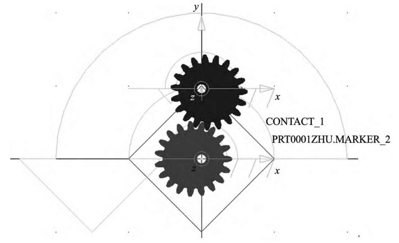
In ADAMS, the stiffness of the material is defined as 20000 n / mm, the force index is 2.2, and the maximum damping is 400 N · s / mm. In the process of kinematics, the mutual penetration of contact in a small distance is allowed. The rotation center of the driving and driven wheels is set as the rotation pair, and then the rotation drive is set at the rotation center of the driving wheel, as shown in Figure 1. The driving speed of the rotating pair is 30 ° / s, the movement time is 32 s, and the number of steps is 320. Then start the kinematic analysis. According to the movement of the gear pair, get the angular velocity curve of the driving wheel, as shown in Fig. 2, and the angular velocity curve of the driven wheel, as shown in Fig. 3.
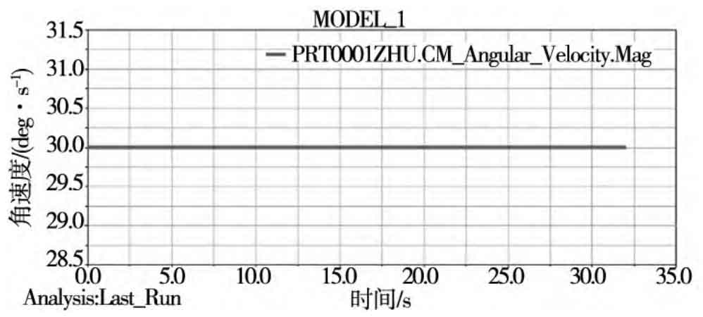
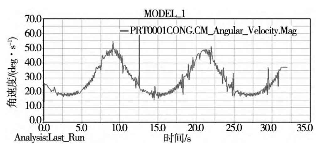
It is proved that the non conjugate gear meets the requirements of non-circular gear transmission. It can be seen from Figure 2 that in Adams motion simulation, the angular velocity diagram of the driving wheel is a straight line, that is, the driving wheel rotates at a uniform speed. The reason why the curve in Figure 3 is not smooth may be that the non-circular gear is relatively complex and has a large number of teeth, resulting in greater cumulative error and distortion of the simulation curve.