
In UG software, open the forging drawing interface, and open the analysis → measuring body → selecting body → volume window in sequence. It is concluded that the forging volume is 948732mm3. According to the principle of the same volume, the inclination angle of the forging side wall remains unchanged at 13 °, the top of spiral bevel gear blank 1 is horizontal, and the top of spiral bevel gear blank 2 is 13 ° with the horizontal plane. As shown in Figure 1, numerical simulation analysis and comparison are carried out for these two cases.
In deform pre-processing, the main parameters of the two are the same. The blank temperature of spiral bevel gear is 1000 ℃, the temperature of male and female die is 350 ℃, the friction coefficient is 0.3, the mesh is divided into 100000, and the upper die speed is 200mm / s, that is, it is carried out under lubrication. After setting, the simulation operation is started. The simulation results are shown in Figures 1 and 2.
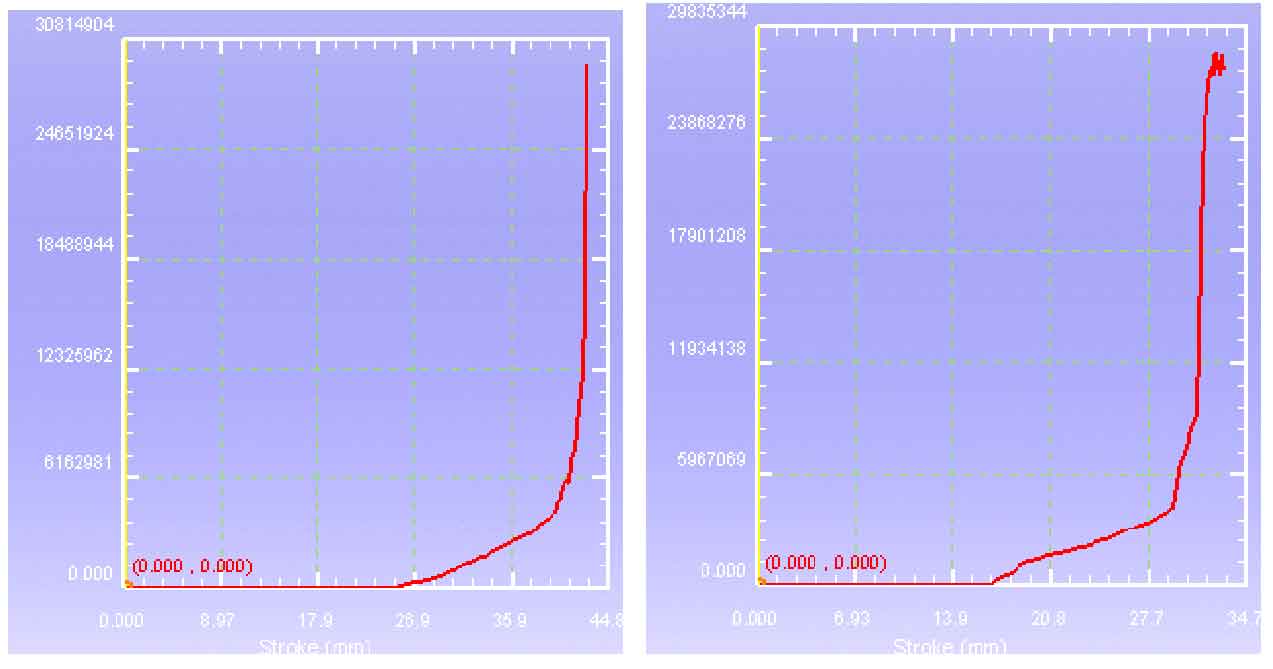
From the load distribution diagram obtained by numerical simulation in Fig. 2 (a) and (b), it can be seen that the load distribution trend of the two is basically the same at different downforce. When the tooth top of the punch contacts the metal, that is, the gear begins to form. With the continuous increase of the downforce of the punch, the load value gradually increases. When the metal of the tooth begins to fill the mold, the load value increases sharply until the end of the tooth filling, and the load value is the maximum value. In the final forming stage of the tooth profile of the gear, the force load 1 value of the punch is 29200kn, the load 2 value is 26400kn, and the load 1 value is greater than the load 2 value.
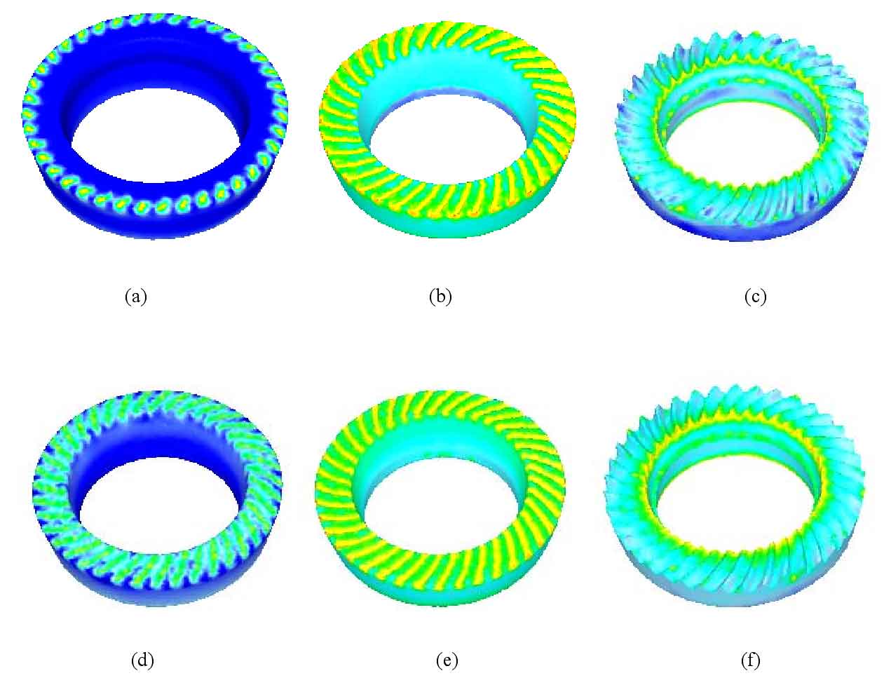
In Figure 3, a, B and C are the forming process diagram of spiral bevel gear blank 1, and D, e and F are the forming process diagram of spiral bevel gear blank 2. From the forming process of the gears of the two schemes, it can be seen that due to the same tooth shape of the punch, the plane inclination of the top of the spiral bevel gear blank is different. Macroscopically, the punch in scheme 1 first contacts the metal at the outer circumference of the top of the spiral bevel gear blank, and with the continuous increase of the pressing amount of the punch, In turn, the metal in contact with the inner circumference of the top of the spiral bevel gear blank. First, the metal in contact with the tooth shape of the punch moves in the inner circumference direction in addition to the downward movement, but the amount of movement is less than the amplitude of the downward movement. The numerical simulation shows that the maximum equivalent strain of scheme I is 1.81 and the maximum equivalent stress is 286. The maximum equivalent strain of scheme 2 is 1.50 and the maximum equivalent stress is 266.
Comparing the above two schemes, scheme 2 is better than scheme 1. That is, the blank size of spiral bevel gear in scheme 2 is selected.