
Stress is the internal force per unit area, which reflects the stress of spiral bevel gear blank. Figures (a), (b), (c) and (d) are the equivalent stress distribution diagram of spiral bevel gear blank metal when the numerical simulation is carried out to steps 40, 50, 60 and 73 respectively. It can be seen from the figure that when the punch just starts to move downward, as shown in figure (a), the stress at the contact with the punch is large, while the stress at the blank part of the spiral bevel gear between the punch teeth without contact with the punch is very small. The maximum stress is at the blank of spiral bevel gear in direct contact with the punch.
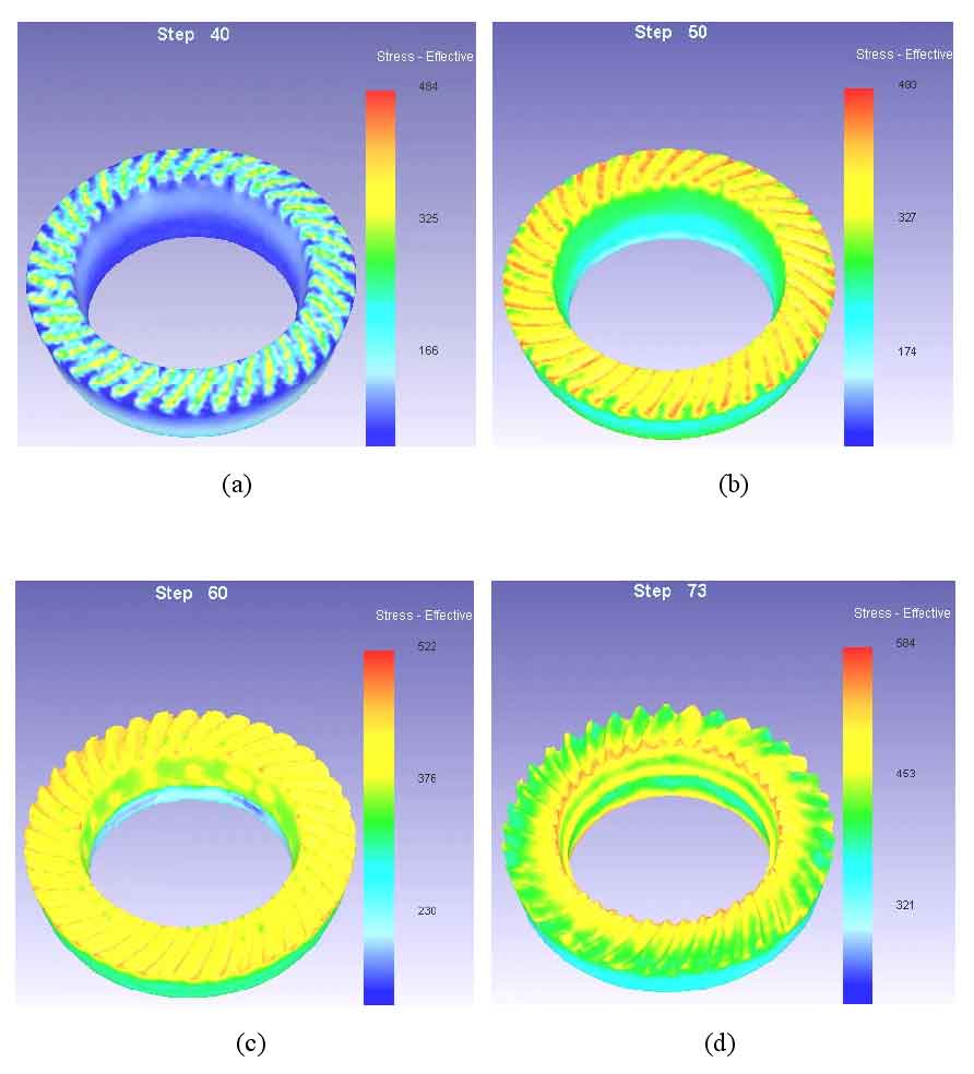
As the punch goes down, the deformation area gradually moves up, and the area with the maximum stress is always the part in direct contact with the punch, as shown in figure (b). When the spiral bevel gear blank begins to fill to the tooth cavity, the metal deformation is mainly concentrated in the tooth cavity of the punch tooth profile die, and the upper and lower ends of the spiral bevel gear blank are filled to the tooth cavity at the same time. Due to the metal filling into the tooth cavity, it is hindered by the friction at the mouth of the tooth cavity, so the equivalent stress value at the tooth root is large. When the reduction reaches 80%, as shown in figure (c), most of the metal has been filled into the tooth cavity, there is a large friction between the tooth root and the blank surface of spiral bevel gear, and the equivalent stress at the tooth root is the largest. At this time, the tooth profile of the gear teeth has been basically formed. When the reduction reaches 100%, as shown in figure (d), at this time, the cavity of the concave die is completely filled, and the tooth top and the corner of the tooth are finally filled. At the small end of the tooth, the metal is the most difficult to fill, and at this stage, the stress value of this part is also the largest, which is 266mpa.