
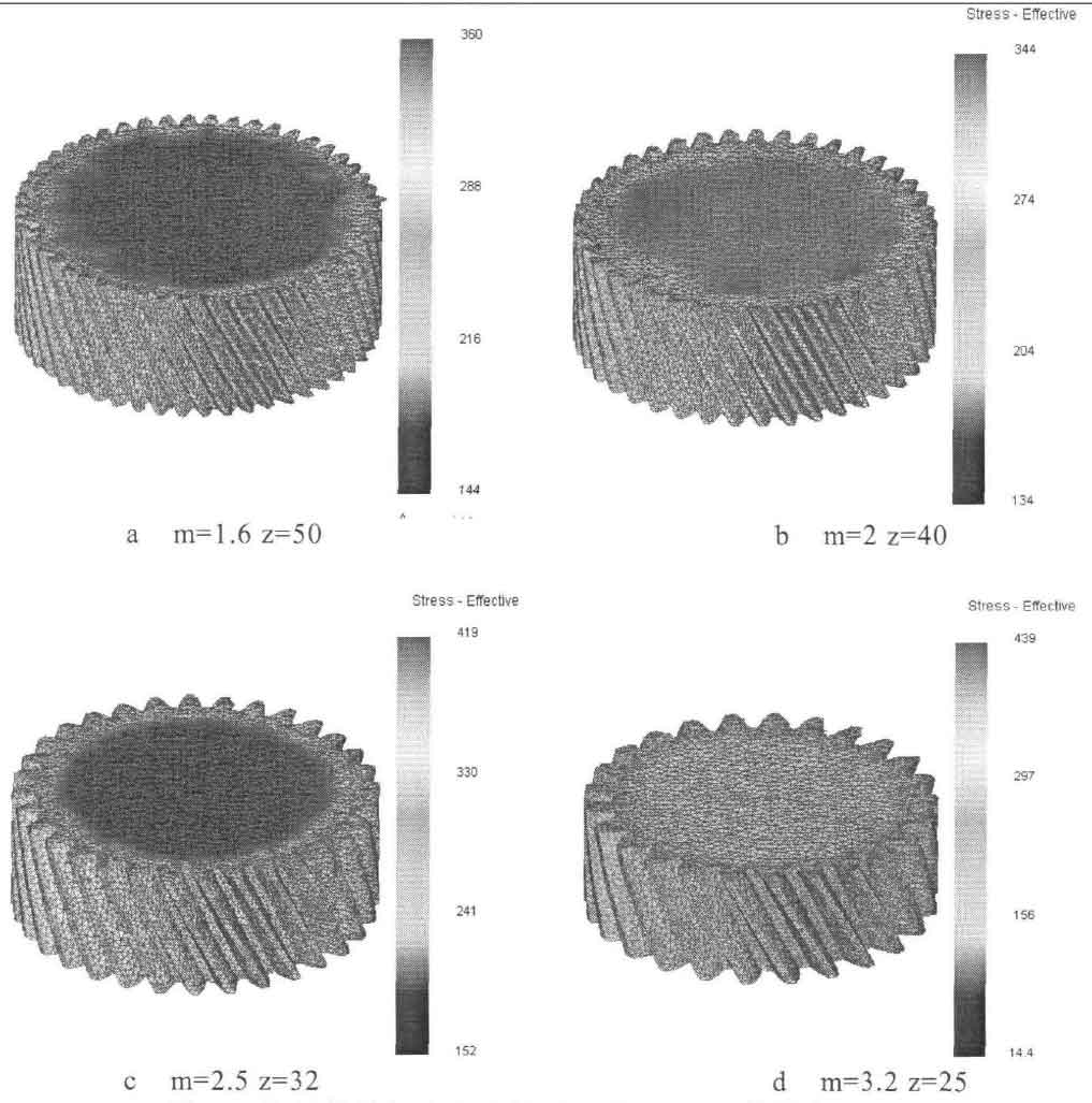
Due to the formula of indexing circle diameter d = mz, it can be seen that the diameter of the bottom surface area of helical gear increases with the increase of modulus and number of teeth. When one of the modulus and number of teeth of the helical gear remains unchanged and the other changes, the bottom surface area of the helical gear will also change. Because the bottom area is different, the size of the helical gear is also different, and the stress contact area between the upper die and the blank is different, the inevitable load is different. In order to make the numerical simulation research more meaningful and accurate, four groups of cylindrical helical gears with different modules are used for finite element simulation, as shown in Figure 1, in which the helix angle is a fixed value β= 25 ° and modulus are m = 1.6, z = 50, M = 2, z = 40, M = 2.5, z = 32, M = 3.2, z = 25 respectively. The diameter of helical gear indexing circle is the same and its size is the same, which avoids the influence of the size of formed gear and blank volume on the analysis of simulation results, and can better analyze the influence of helical gear modulus on spiral gear forming. At the same time, in order to reduce the time of forming initial free pier rough stage, the outer diameter of helical gear blank should be close to the tooth root circle.

Fig. 2 shows the equal effect force distribution diagram of four groups of module spiral bevel gears when the reduction is 100%. From the diagram, it can be seen that when m = 1.6 z = 50, the equal effect force value at the helical gear teeth is 220mpa-270mpa; When m = 2 and z = 40, the equivalent force value at the helical gear teeth is 230mpa-280mpa; When m = 2.5 and z = 25, the equivalent force value at the helical gear teeth is 240mpa-300mpa; When m = 3.2 and z = 25, the equivalent force value at the helical gear teeth is 250mpa-310mpa; As can be seen from Figure 2, with the increase of modulus, the equivalent stress of helical gear is also greater, the deformation resistance is also greater, and the requirements for die strength are also higher.
The load stroke curve of helical gear under four modules is shown in Figure 3. It can be seen from the figure that when m = 1.6 and z = 50, the final load is 5000kN and the final stroke is 3.7mm; When m = 2 and z = 40, the final load is 5700kn and the stroke is 5mm; When m = 2.5 and z = 32, the final load is 5800kn and the stroke is 5.5mm; When m = 3.2 and z = 25, the final load is 6500kn and the stroke is 8mm.
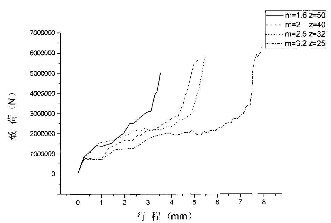
With the increase of modulus, the full tooth height and tooth root width of helical gear teeth will increase, the geometry of gear teeth will increase, and the tooth cavity needs to be filled with more metal. Therefore, as the modulus increases, the stroke will also increase. With the increase of modulus, the full tooth height of helical gear teeth increases, and the metal strain also increases. It is more difficult for metal to fill into the tooth cavity, and its load value also increases. It is consistent with the conclusion obtained from the above analysis that the equivalent stress of helical gear increases with the increase of modulus.