The damage value in deform does not indicate whether there is damage, but the possibility of defects in this part of the workpiece during forming.

c. Curve of damage value with different radius at large end face of cone head
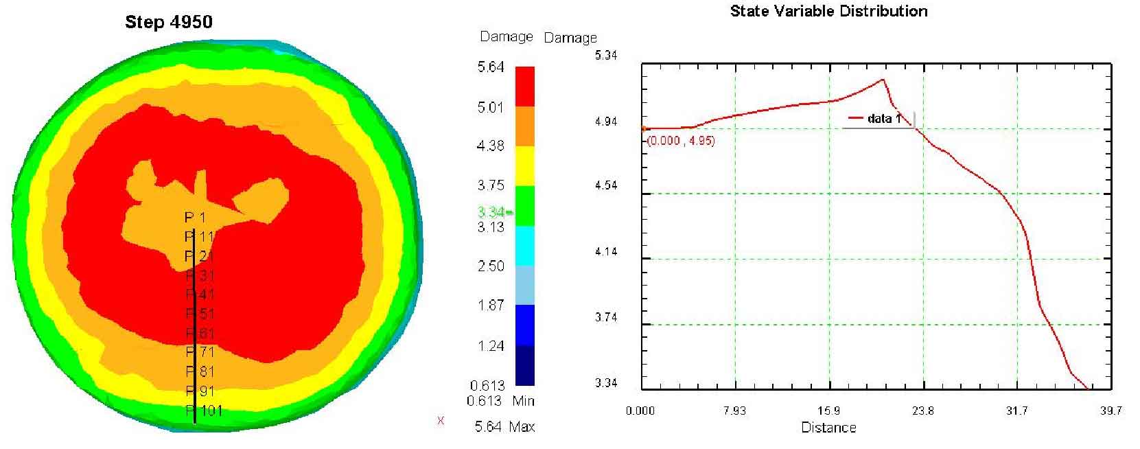
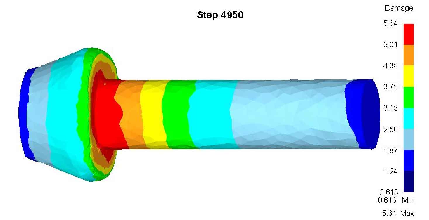
It can be seen from figure a that the contact part between the shaft and the large end face of the cone head is seriously damaged, with the maximum damage value of 5.64, and the damage value extending from this part to both ends is reduced. It can be seen that the contact part between the shaft and the cone head is the key part of forming. It can be seen from figure B that the most damaged area does not completely penetrate the center of the large end face of the bevel gear blank, but the damage value of the center is not small, about 5. The area on the end face where the radius is close to the outer diameter of the shaft is the most seriously damaged. From this part, the damage value decreases sharply with the increase of radius, and the outer circle of the end face is about 3.34. From the damage value curve of the large end surface of the cone head in Figure C, the damage distribution along the radius direction is more obvious. It can be seen from the damage value curve in Figure C that the damage value reaches the maximum within the radius of about 15.9 ~ 30.5mm.
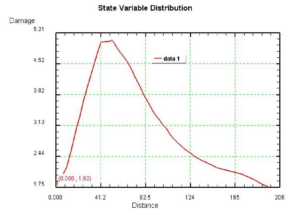
Sampling points on the axis line, from the damage value of each point to curve D. From the D curve, the damage value of small end face of cone head is low, about 1.7. With the increase of the distance from the small end face of the cone head, the damage value rises rapidly. When the distance reaches 41.2mm, it reaches the maximum value and continues to the distance of about 54mm. When the distance increases again, the damage value begins to decrease rapidly, and the damage value at the end of the shaft of the driving spiral bevel gear blank is about 1. It is the connection between the cone head and the shaft that the damage value in the adjacent area is the largest. There are two main reasons for this. One is that with the reverse rotation of rolled piece and roll, the folded burr is constantly rolled into this part. The folded burr itself is highly oxidized due to its large area and high surface energy, and the oxide impurities are also rolled into the interior of the shaft. With the continuous kneading of the workpiece by the die, the burr is constantly rolled in, which seriously destroys the internal organizational structure and lattice structure. The oxide impurities hinder the continuous displacement of lattice atoms, resulting in defects such as stress concentration and microcracks at the impurities. The second is that the side edge of the die binding wedge is too sharp. In the process of repeated rubbing of the die binding parts, the sharp side edge constantly acts on the connecting part of the cone head and shaft, resulting in serious damage to this part.
In conclusion, it can be seen that the cross wedge rolling process has good forming integrity and reasonable metal flow in the rolling process. However, there are still some defects in the forming process, such as large radial dimension error, folding burr on the large end face of the cone head, and large damage value at the joint between the cone head and the shaft. In order to improve the above defects and further improve the forming quality of spiral gear blank, the existing production process of cross wedge rolling is improved.


