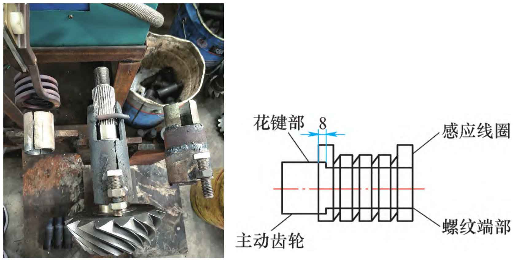
First, a limit tooling is added to the simple induction positioning tooling, that is, the welding limit bolt is used to ensure the effective positioning of the extension position of the external thread, as shown in Figure 1. Put the end of the induction bevel gear into the position of the inner thread of the driving bevel gear (see Fig. 2), and the end of the induction bevel gear must be aligned with the inner thread of the driving bevel gear, and the induction bevel gear must be put into the position of the inner thread of the driving bevel gear. The external spline tooth needs to extend into the induction coil by about 8mm.
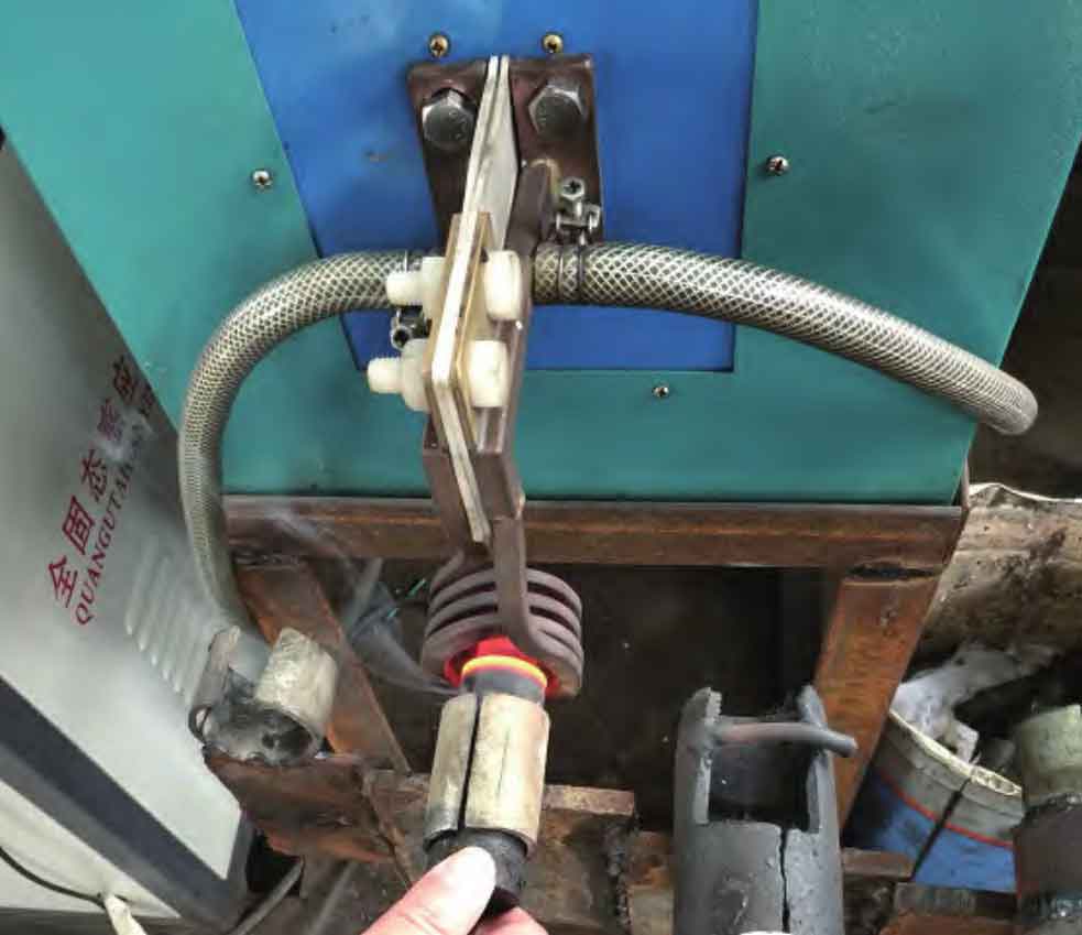
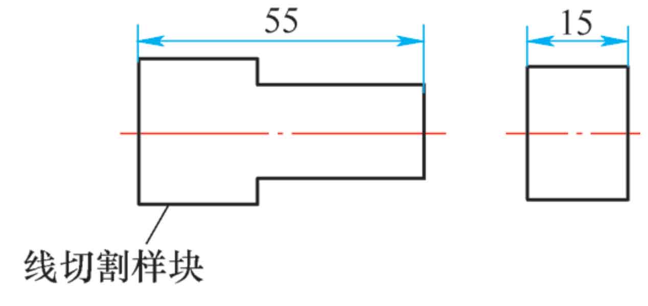
Second, the process parameters are optimized and adjusted to ensure that the working voltage is 380V, the working current is 12 ~ 30a, the total heating time is controlled at 11S, and the heating frequency is determined as 29khz. Firstly, the heating test is carried out with the test head to check and verify the process parameters and hardness test (see Figure 3), and then the formal workpiece start pedal switch is used to start the heating again. It is necessary to manually rotate the driving spiral bevel gear slowly to ensure the uniformity of heating. After heating, take out the driving spiral bevel gear for air cooling. After it is completely cooled to room temperature, conduct wire cutting at the threaded end of the driving spiral bevel gear aligned with the center of the shaft. The cutting length and thickness are 55mm and 15mm respectively, as shown in Figure 4. The cut sample block is shown in Figure 5. Send the wire cut sample block to the metallographic examination room for hardness testing.
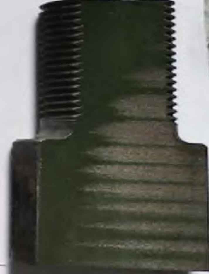
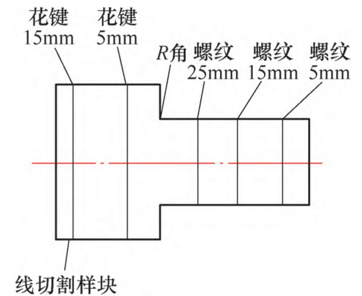
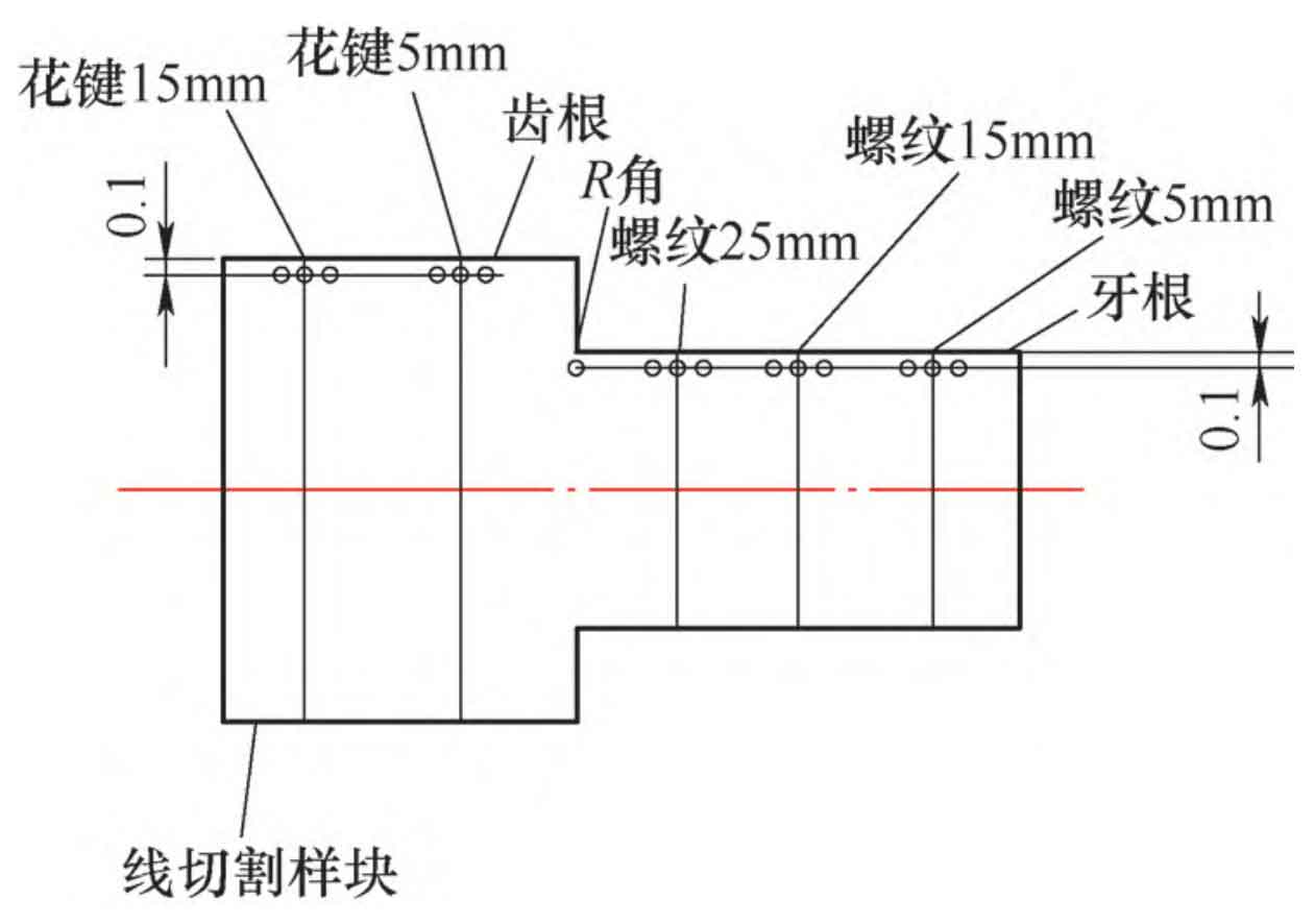
After that, the p-2t metallographic pattern polishing machine is used for polishing and cleaning. After drying, the sample block is placed flat on the inspection platform of the microhardness tester, and the inspection is carried out after adjusting the position and focal length. It is required to take three points respectively at 5mm, 15mm and 25mm of the thread and 0.1mm from the root of the thread for hardness testing, one point at the R corner, that is, 0.1mm from the end, and three points at 5mm, 15mm and 0.1mm from the root of the external spline for hardness testing, as shown in Fig. 6 and Fig. 7.