
Through the three-dimensional numerical simulation of the ring sample, it is concluded that the ring sample with a certain surface pit shape distribution can increase the contact stress in the contact surface area without lubrication. In order to study the stress distribution of spur gear in actual meshing, it is necessary to carry out finite element analysis of spur gear in loaded meshing state. The main content of this chapter is: two-dimensional contact finite element analysis of spur gear without lubrication. Because the stress of spur gear is consistent in the axial direction, the spur gear entity can be simplified into a two-dimensional single-layer sheet surface line contact model for analysis.
The two-dimensional linear contour assembly model of spur gear is established by CAXA electronic drawing board, and then imported into ANSYS for two-dimensional plane modeling of spur gear; Using the general pre processor module of ANSYS, the unit type is selected and the material properties are defined; The whole two-dimensional spur gear plane model is meshed with the automatic mesh tool. The two-dimensional structural solid elements of large and small gears are plane182. The contact type is defined and the point line contact mode is selected; In the solution options, select the analysis type, set the contact boundary conditions and contact load of the spur gear, and solve the two-dimensional line contact finite element of the spur gear. Finally, use the calculation results displayed in the post processor to obtain the cloud diagram of the contact stress distribution of the spur gear, and make a comparative analysis of the contact equivalent stress and contact stress between the smooth spur gear and the concave spur gear.
Table 1 shows the geometric dimensions of two-dimensional solid modeling of spur gears; Table 2 shows the material properties required to generate the finite element model of spur gear; Table 3 shows the load parameters set for solving the contact stress of spur gears.
A. Geometric dimension of spur gear:
| Geometric parameters | Gear pair gear | Gear pair pinion |
| Number of teeth | Z1=24 | Z2=16 |
| Tooth width | b1=20mm | b2=20mm |
| Displacement coefficient | X1=-0.5 | X2=0.8517 |
| Addendum height coefficient | ha*=1 | ha*=1 |
| Top clearance coefficient | c*=0.25 | c*=0.25 |
| Graduation circle diameter | d1=108mm | d2=72mm |
| Inner hole diameter | D1=30mm | D2=30mm |
| Theoretical central moment | a=90mm | a=90mm |
| Installation center distance | aa=91.5mm | aa=91.5mm |
| Modulus | m=4.5 | m=4.5 |
B. Material characteristics of spur gear:
| Texture of material | Modulus of elasticity EX | Material density DENS | Poisson’s ratio ν | Friction coefficient MU | Contact fatigue limit σ Hlim(MPa) | Bending fatigue limit σ FE(MPa) | Hardness |
| 20CrMnTi | 207GPa | 7800 kg/m3 | 0.25 | 0.1 | 1500 | 850 | (56-62) HRC |
C. Load parameters of spur gear:
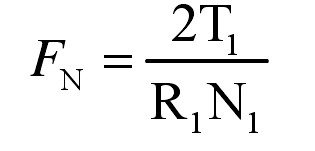
FN — torque of driving gear
T1 – positive pressure
R1 – radius of driving gear inner hole
N1 — number of nodes of driving gear inner hole radius
| Parameters | Driving gear | Driven gear |
| Torque | T1=150.23N·m | T2=225.18 N·m |
| Rotational speed | n1=1450r/min | n2=967 r/min |
| Aperture | R1=15 | R2=15 |
| Number of nodes | N1=42 | N2=72 |
| Normal force | FN=294N | FN=294N |