
According to the static contact analysis principle of cylindrical gear, the passive cylindrical gear needs to be completely fixed, and the driving cylindrical gear applies a certain load torque.
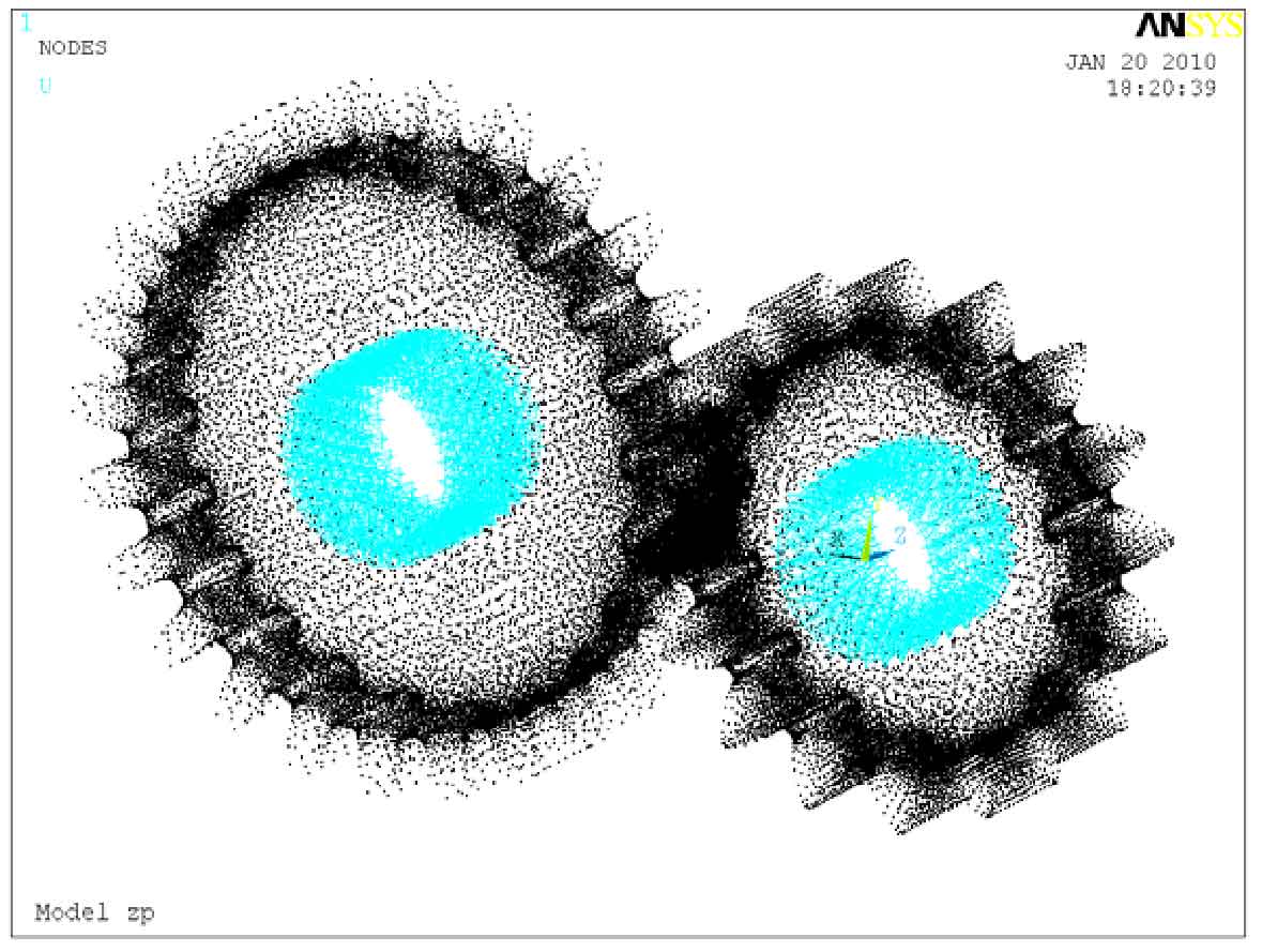
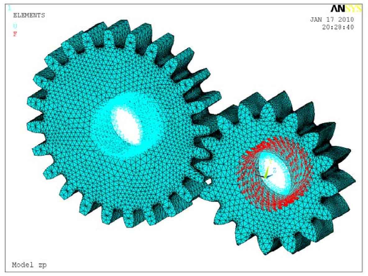
That is, in the node coordinate system, select all nodes on the inner hole surface of the big gear and set the all DOF constant to 0 to restrict the degrees of freedom of all nodes of the inner hole of the big gear; Select all nodes in the inner hole of the pinion and set the constant values of UX and UZ to 0 to constrain the degrees of freedom of all nodes in the X and Y directions of the pinion. Fig. 1 is a schematic diagram of the boundary conditions after the constraints are applied to the two cylindrical gears; Using the rotation setting in ANSYS, select all nodes in the inner hole of the pinion again and apply the torque in the uy direction. The torque is calculated by the formula, T1 = – 33.87 n · M. Fig. 2 is the schematic diagram of contact loading of cylindrical gear after torque is applied.
In the analysis of cylindrical gear contact problem, it is very important to define the real constant and element keyword. According to the actual simulation situation, through multiple calculations and repeated debugging, ftoln = 0.08 is finally selected to define the maximum penetration range; Set icon = 0.1 to define the initial proximity factor; Set keyopt (9) = 1 to solve the problem of initial seepage influence, and set keyopt (5) = 3 to determine the adaptive contact boundary.
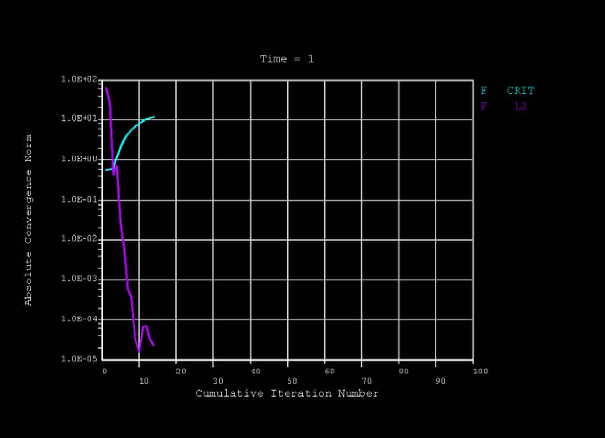
The solution setting is consistent with the two-dimensional contact analysis. The time step is set to 1, and the number of sub steps is set to 10, the maximum number of sub steps is set to 20, and the minimum number of sub steps is set to 10. The three-dimensional contact nonlinear solution curve of smooth cylindrical gear is shown in Figure 3.