
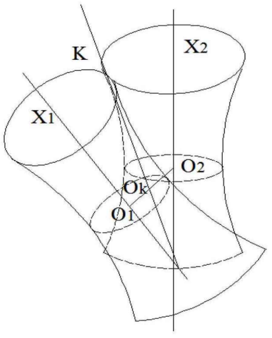
The main function of hypoid gear is to carry out spatial staggered shaft transmission. The so-called staggered shaft refers to two axes that are neither parallel nor intersecting in space. For solving the relative velocity at any point in the meshing space of two gears, the theory of instantaneous shaft surface is applied. If the relative velocity of any point in space is equal to the linear velocity formed when the point makes a certain spiral motion around a fixed axis, then the axis is called the instantaneous axis. In Figure 1, the axis crosses the axis, and the axis is the instantaneous axis. Let the axis rotate around the axis and the axis respectively to obtain a pair of hyperboloids, which are also called instantaneous axis surfaces.
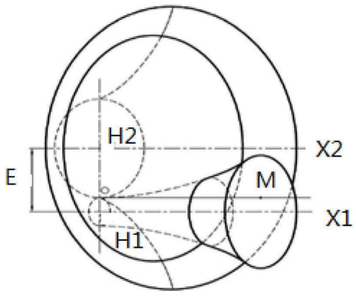
As shown in Figure 2, M is the tangent point of two cones, which is referred to as the midpoint node of tooth width in Gleason tooth system, e is the common vertical line between X1 axis and X2 axis, and its length is referred to as offset.
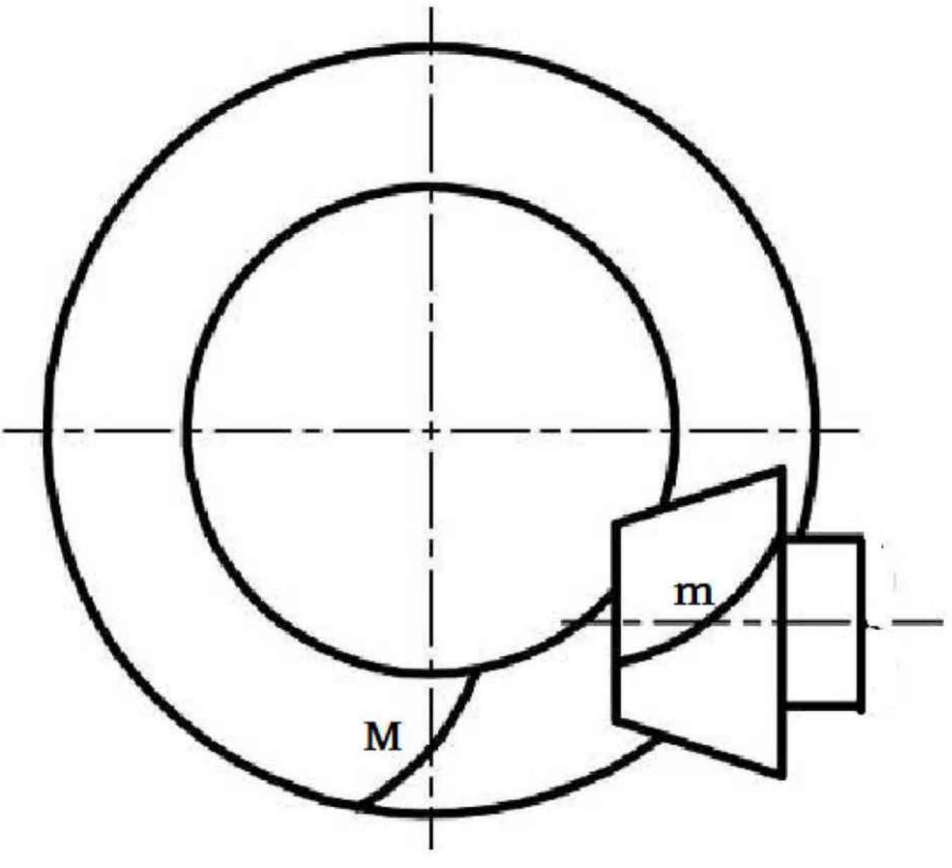
Due to the offset distance of hypoid gears, two positions of hypoid gears are distinguished according to the position of the small wheel axis relative to the large wheel axis. Figure 3 shows the lower offset of the small wheel. When the axis of the small wheel is lower than the axis of the big wheel, it is called the lower offset, otherwise it is the upper offset; From the small end of the big wheel to the big end of the big wheel, if the projected rotation direction of the tooth line from the midpoint node m of the tooth width to the big end is clockwise, then the rotation direction of the big wheel is called right rotation, otherwise it is left rotation, and the judgment method of the rotation direction of the small wheel is the same; Look from the big end of the hypoid gear to the small end of the hypoid gear along the direction of the tooth line, with the tooth root at the bottom and the tooth top at the top. The left and right sides of this tooth correspond to the left and right tooth surfaces respectively.
Of course, it is difficult to manufacture hypoid gears with the hyperbolic surface as the pitch surface in actual production, so bevel gears are used instead.
The software is used to respectively align the boundary tangent and tooth top line of the left and right tooth surfaces of the hyperboloid gear on the corresponding base plane, and calculate new parameters for the subsequent derivation of the machining equation. The left and right tooth surfaces of hypoid gears are also subject to the same process. The key parameters are obtained by curve fitting, which lays a foundation for the subsequent Equation Derivation and the preparation of machining program.