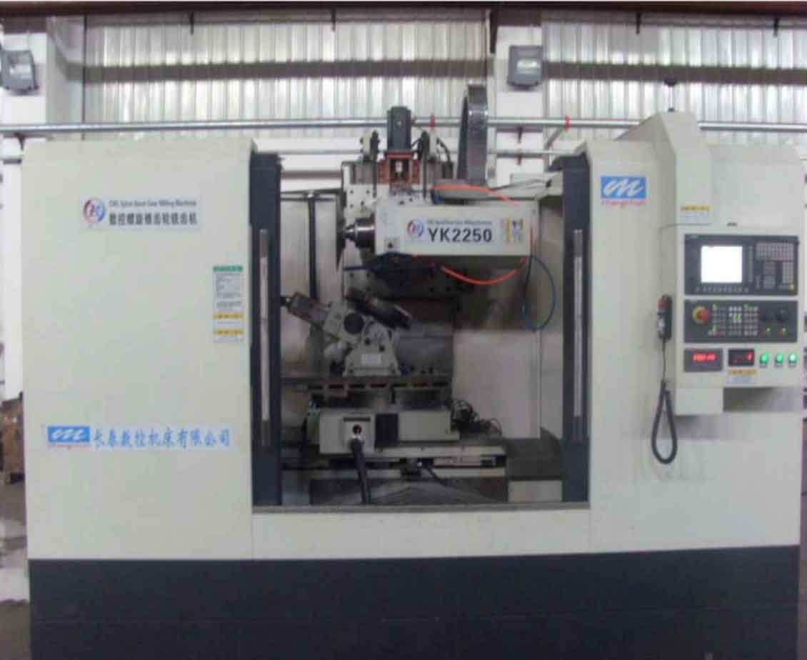
Hypoid gears need to be machined on the YK2250 gear milling machine, so the coordinate system should be established in the Q plane according to the motion relationship required for machining hypoid gears and the workpiece coordinate g54. As shown in Figure 1:
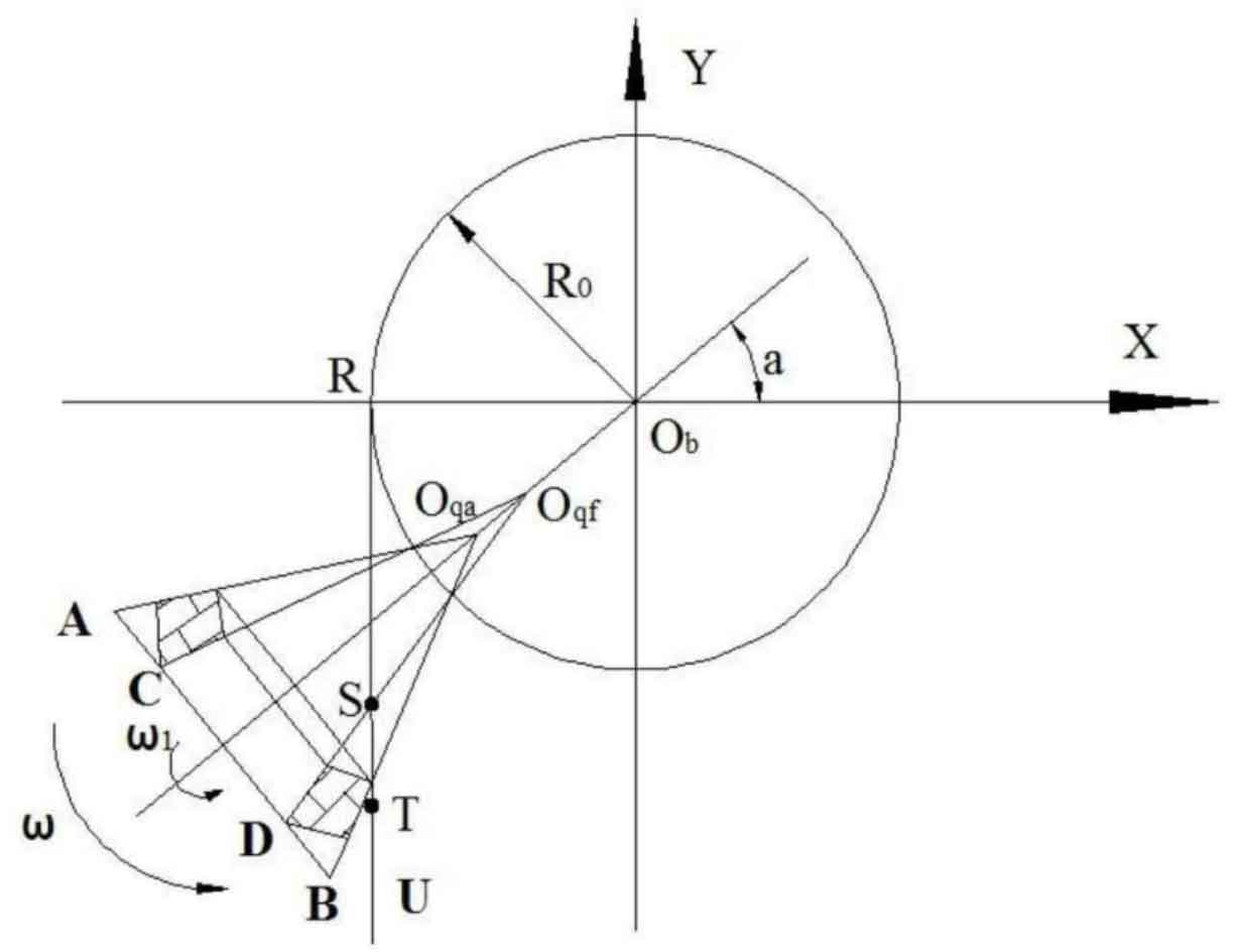
As shown in Figure 2, the coordinate system is established with the zero point of machine tool g54 as the origin of the coordinate system. The initial position of the gear blank in the coordinate system is represented by the initial angle a of the gear blank; Ru refers to the cutting direction of the production line along the Y axis, and the cutting can be carried out from R to u or from u to R according to the different machined tooth surfaces; The line segment st is the production line, that is, the curve generated when the disc milling cutter rotates rapidly; In the figure ω 1 and ω Respectively represent the angular velocity of the gear blank rotating along its own axis and the angular velocity rotating around the apex of the base cone (i.e. the origin of the coordinate system OB). In this way, the coordinate system can completely describe the three-axis linkage required by the hypoid gear machining process. The production line st is cut along the boundary tangent oqdd by two rotations and the movement of the production line end s along the Y axis.