
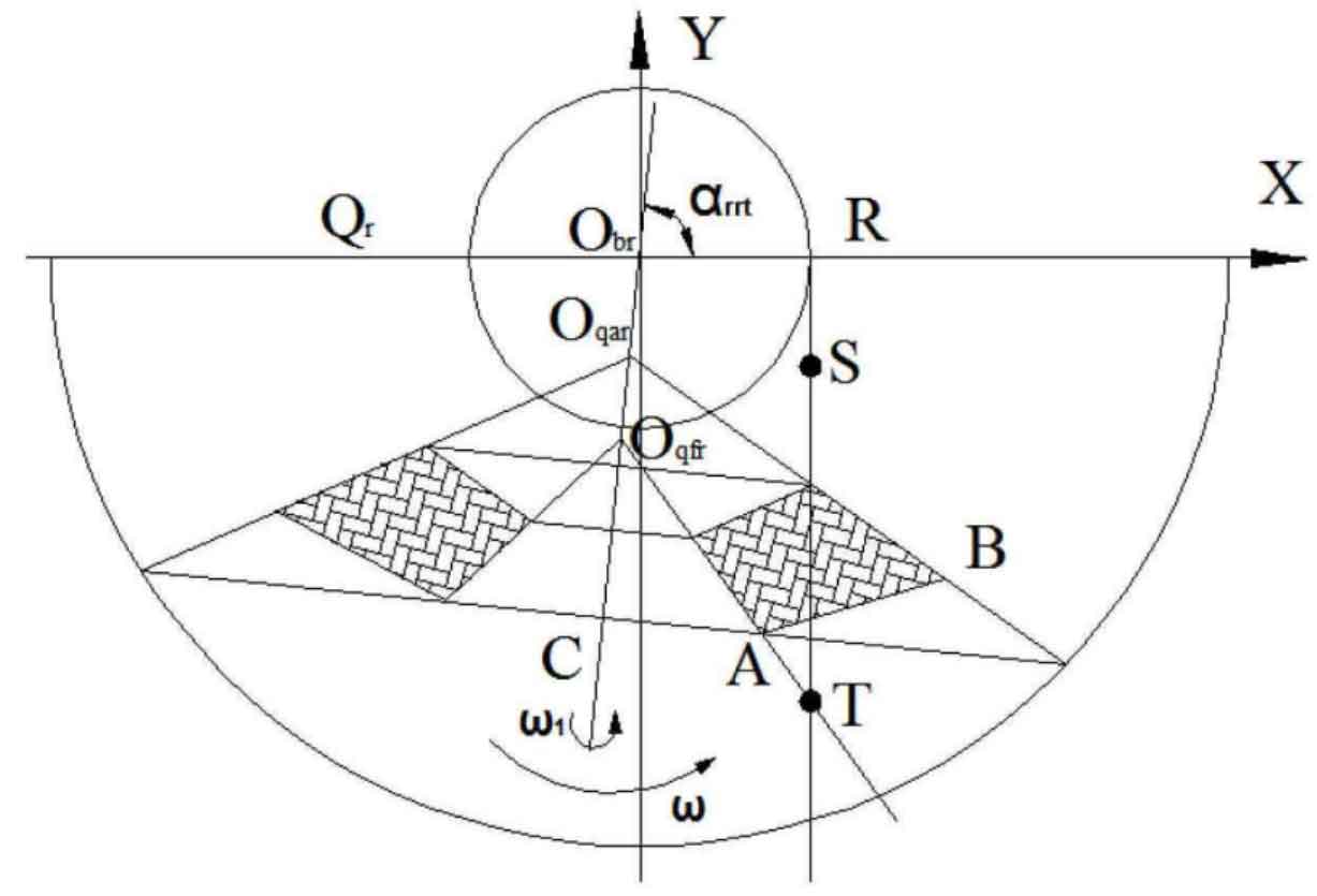
There are also four methods to place the gear blank in the coordinate system when machining the right tooth surface of hypoid gear wheel, which are similar to those for machining the left tooth surface, and will not be specifically described here. According to the fact that the rotation direction of hypoid gear wheel wheel is right rotation, the current situation of the CNC spiral bevel gear milling machine tool, and the comprehensive factors that the milling cutter is a single edge and an external edge, the right tooth surface of hypoid gear wheel is selected to be placed in the second quadrant for machining, as shown in Figure 1: the production line of the milling cutter is st, where t is the beginning of the production line, α NT represents the direction angle of the gear blank at a certain time in the machining process, that is, the included angle between the gear blank rotation axis and the positive direction of the X axis, as shown in Figure 1 above. The first R represents that the rotation direction of the hypoid gear wheel is right rotation, the second R represents that the right tooth surface of the hypoid gear wheel has been machined, and T represents a certain time.
The general idea of machining is that the right tooth face of the hypoid gear wheel keeps pure rolling on the base plane, and the beginning or end of the milling cutter profile is cut along the tooth root line on the base plane.
There are also two processing methods for placing the right tooth surface of hypoid gear wheel blank in the second quadrant, as shown in Figure 2. The first processing method is as follows:
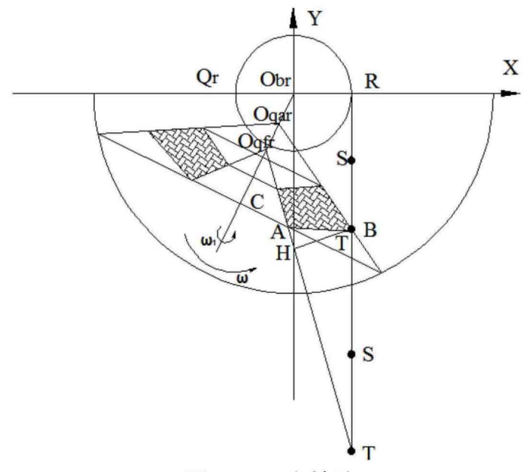
As shown in Figure 2 above, the right tooth surface base cone of the hypoid gear wheel rotates counterclockwise on the corresponding base plane Q with the top OBR of the base cone as the rotation center. The angular velocity is ω Indicates that at the same time, the gear blank rotates around its central axis obrc, and the angular velocity is ω 1, the rotation direction can be determined by the following method. The direction is clockwise from the big end of the hypoid gear to the small end of the hypoid gear. When the two rotating axes are linked, the production line st performs cutting movement along the positive direction of the Y axis, and its motion law will be derived in the subsequent part. Through the above three-axis linkage, the cutting of the milling cutter from the tooth top part of the big end of the tooth to the tooth root part of the tooth is finally realized, and the machining of the right tooth surface of hypoid gear wheel is completed. After cutting a tooth surface, the milling cutter retracts along the axial direction, the gear blank returns to the tool setting position for indexing, and then continues to cut in the previous process until all right tooth surfaces are cut.
One disadvantage of this method is that the milling cutter production line will go through an empty stroke th, as shown in Figure 3. Because hypoid gear wheel needs to process a large number of teeth, the travel time will be long. In order to improve the processing efficiency, the empty stroke is omitted, and method 2 is adopted for processing, as shown in Figure 3. Adjust the tool point, i.e. adjust the position of the beginning t of the production line. When machining starts, the production line st remains stationary, and the gear blank only needs to make two movements, including angular velocity in the base plane QR ω Rotate counterclockwise, and the gear blank rotates at an angular speed around its own axis ω 1 rotate clockwise until it reaches the position on the right side of Figure 3 below.
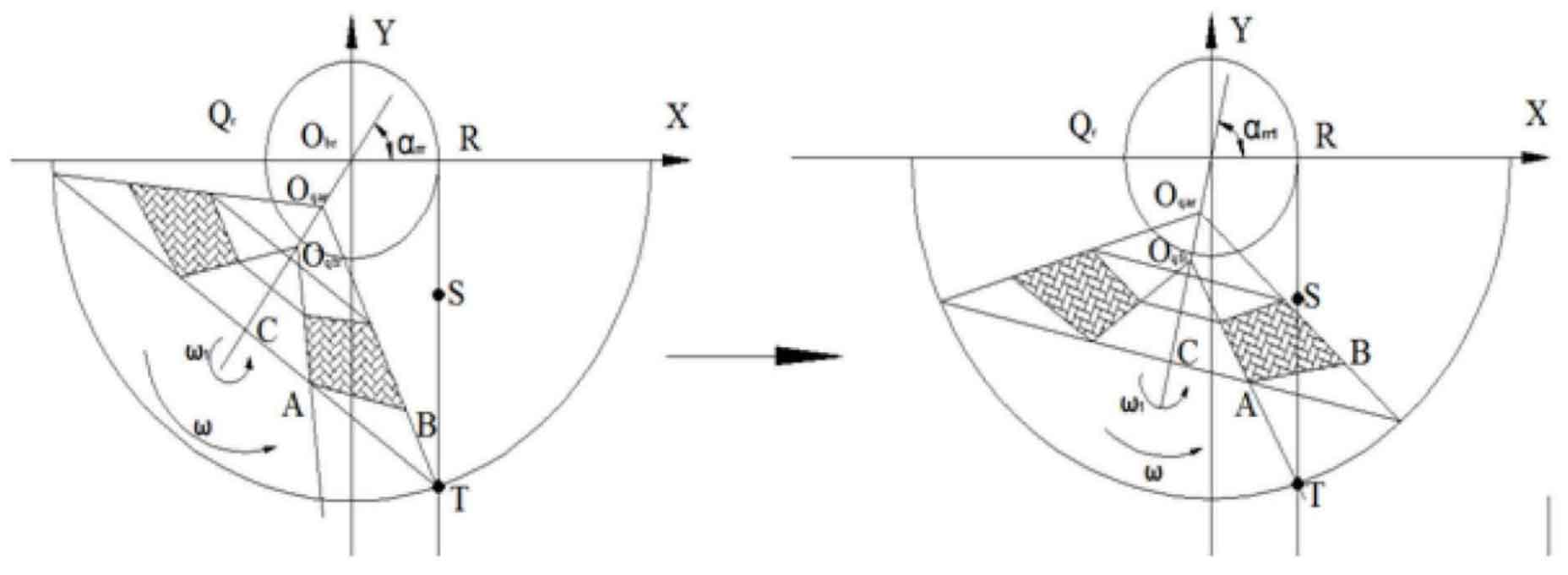
That is, on the premise that the hypoid gear base cone keeps pure rolling on the base plane, the production line does not move until the production line and the tooth root line on the base plane intersect with the t point. When the start t of the production line is cut to the tooth root line, the three-axis linkage starts. That is, the revolution and rotation of the original gear blank continue, and then the generating line st moves along the positive direction of the Y axis in the coordinate system, and the rest of the right tooth surface of the hypoid gear wheel is processed through the cooperation of three movements. After cutting a tooth surface, the milling cutter retreats upward along the Z axis, the gear blank returns to the tool setting position for indexing, and then continues to cut in the previous process until all right tooth surfaces are cut.
The derivation idea of machining equation: first calculate the initial angle of the gear blank at the tool setting position in the coordinate system, then find the relationship between the ordinate at the beginning of the production line cutting along the tooth root and the initial angle of the gear blank, and then calculate the angular velocity required by the gear blank when the production line is not moving ω Finally, find out the cutting position (cutting angle) after machining in the machining coordinate system, and evenly divide the turning angle required for machining the right tooth surface until all the right tooth surfaces of the hypoid gear wheel are machined.
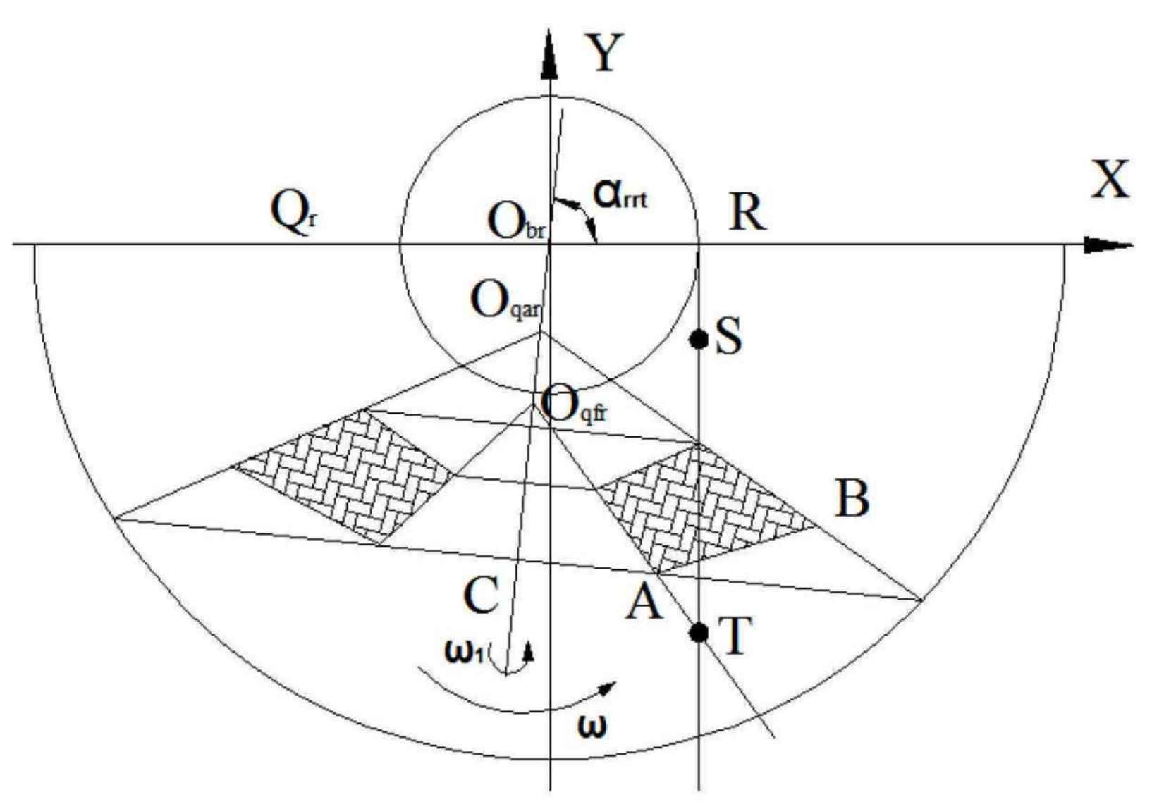
In the above figure α RRT refers to the direction angle of the gear blank at a certain time in the machining process, that is, the included angle between the gear blank rotation axis and the positive direction of the X axis. The significance of the relevant small angle sign has been explained; The angle corresponding to the gear blank rotation, i.e. the circumference of the workpiece, is indicated by the symbol γ RR means; The circumference of the gear blank corresponding to the right-handed right-handed tooth face at any time is indicated by the symbol γ RRT, where R, R and t have the same meaning as the gear blank direction angle. The line segment st in the figure represents the production line, and S is the end of the production line; The tangent circle radius of the occurrence line is expressed by R. In the figure, the base plane is represented by QR, R represents the base plane corresponding to the right tooth face of hypoid gear wheel, and similarly, the apex of the base cone is represented by OBR.