
Based on the three-dimensional solid model, through the measurement and interference analysis module, the sharpening and contraction of the top of the gear teeth can be visually inspected and analyzed, and the interference and coincidence of the gear pair can be analyzed through motion simulation, which provides an effective method to ensure the quality of the gear pair and its practical application.
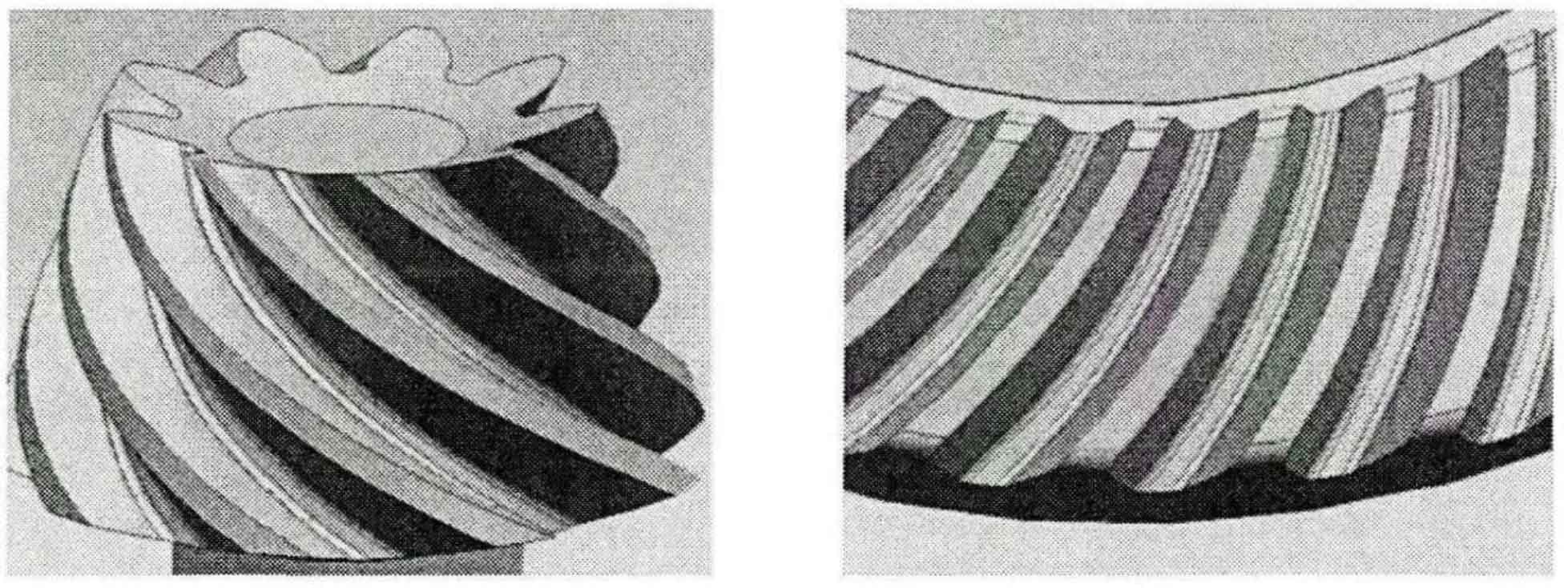
(1) Tooth tip sharpening inspection
Take a tooth from either the small wheel or the big wheel respectively. It can be seen from Figure 1 that there is no tip sharpening of the small wheel and the big wheel of the cycloid hypoid gear pair.
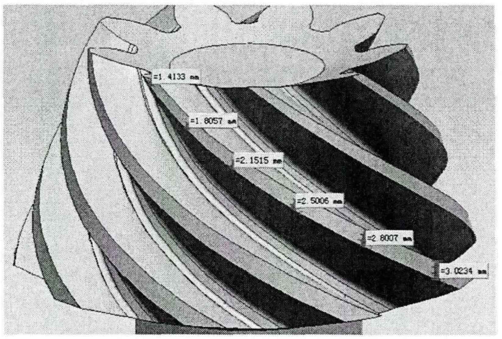
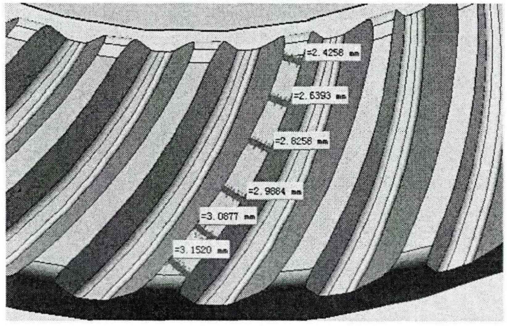
(2) Addendum shrinkage test
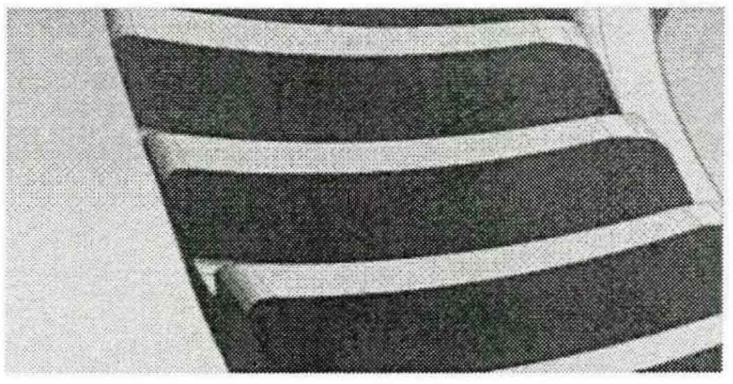
Because the cycloid hypoid gear teeth are equal height teeth, the measurement distance command is used in NX to measure the tooth top thickness and observe the shrinkage from the small end to the large end of the tooth. Take 6 points along the tooth line of the small wheel and the big wheel respectively, and the results (as shown in Figure 2) show that the tooth shrinkage of the small wheel and the big wheel meets the requirements.
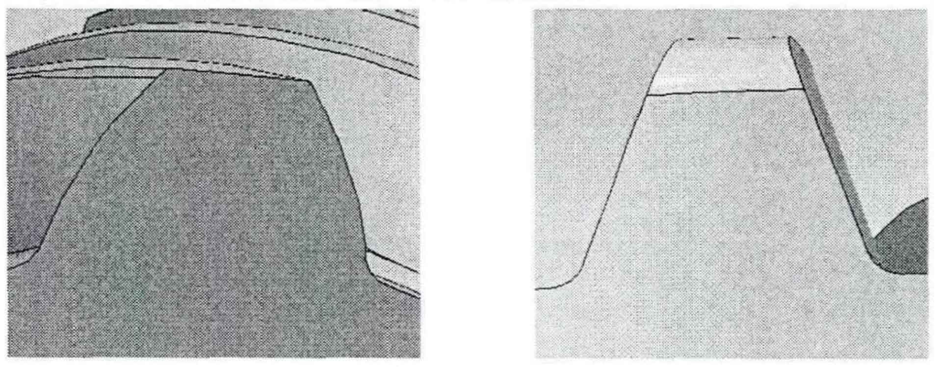
(3) Undercut test
Check the undercut of the small wheel and the big wheel respectively, as shown in Figure 3. It can be seen from the figure that the small and large wheels of cycloid hypoid gear pair obtained by using the spirac method to control the consistency of forward and reverse transmission have no undercutting.
(4) Interference test
Install correctly according to the working state of cycloid hypoid gear pair. The intersection angle of the axis of the big wheel and the axis of the small wheel ∑ =90 °, the offset distance e=31.75mm, and the installation distance of the big wheel am2=55mm and the installation distance of the small wheel am1= 104.9mm are calculated from the wheel. The component model obtained after assembly is shown in Figure 4. The meshing angle of the big wheel and the small wheel is calculated according to the position of the reference point, so that the two gears rotate around their respective axes and mesh at the meshing angle.
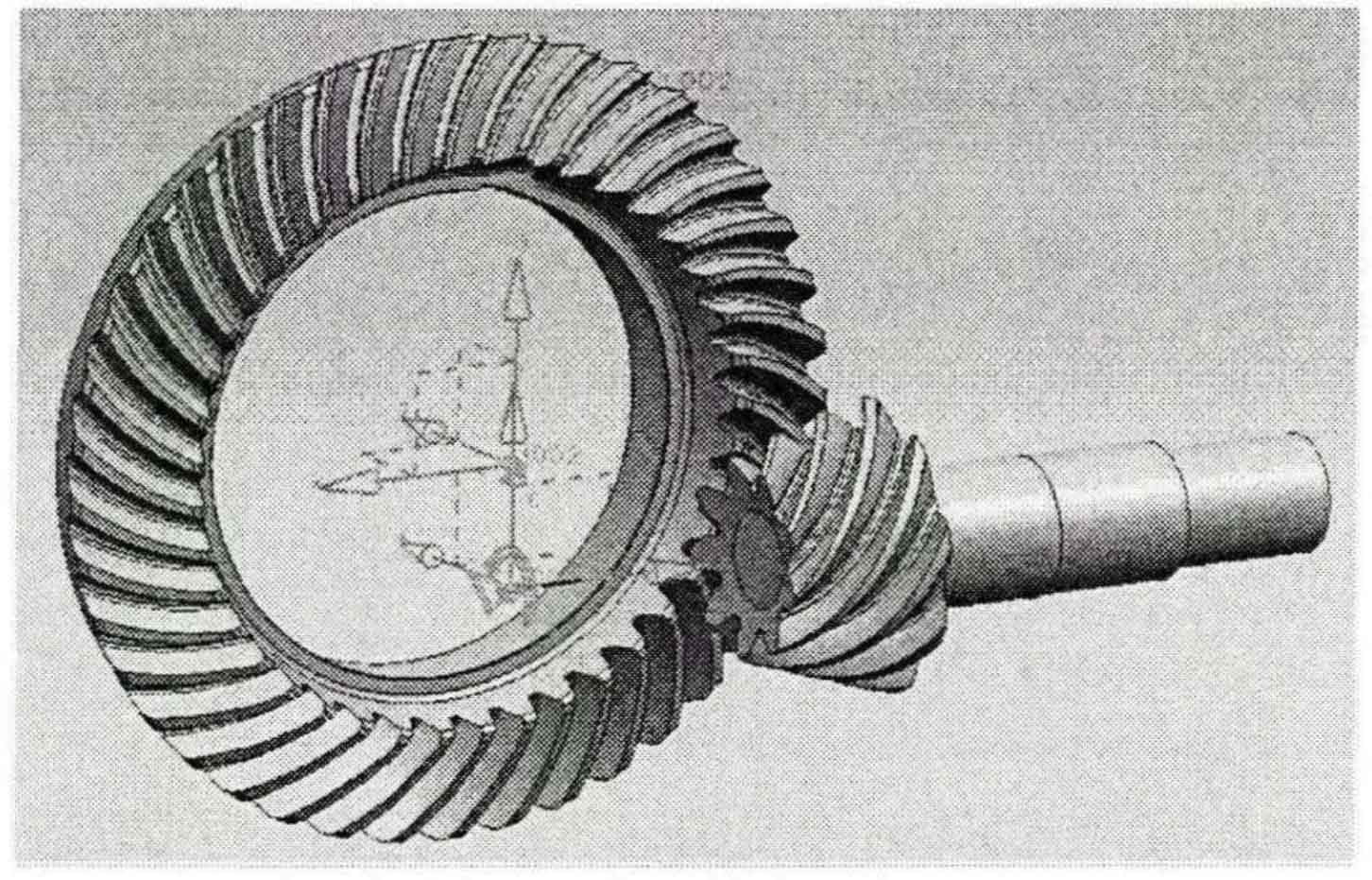
Enter the dynamic environment of NX motion simulation, set the big and small wheels as non fixed connecting rods respectively, and establish a rotating motion pair, in which the small wheel is the driving wheel, and the rotation speed of the small wheel needs to be given. Because the transmission ratio changes during the transmission of Cycloid Bevel Gear and hypoid gear pair, according to the actual meshing situation, the NX simulation adopts 3D contact, and the small wheel drives the big wheel to rotate.
Set up interference analysis, establish a solution scheme and solve it. Mesh and rotate. According to the interference analysis report, based on the forward and reverse directions of the gear pair
The example calculated by spirac method with consistent transmission has no interference in the transmission of cycloid tooth hypoid gear pair.
(5) Coincidence inspection
Cycloid Bevel Gears and hypoid gear pairs are point contact gear pairs. In order to visually reflect the contact condition of the gear pair, according to the red lead powder particle diameter of 0.0064mm used in the tooth surface coloring inspection, the large and small wheels are rotated by a certain angle around their respective axes, so that the meshing tooth surface at the reference point of the cycloid hypoid gear pair is meshed into 0.0064mm, and the meshing simulation. An instantaneous tooth contact mark is obtained by establishing an interference entity, as shown in Figure 5.
It can be seen from Figure 5 that the coincidence degree of cycloid hypoid gear pair is greater than, which is consistent with the formula calculation.