
In order to more intuitively reflect the meshing characteristics of spiral bevel gear pairs, tooth contact analysis (TCA) technology is usually used to simulate the meshing process of spiral bevel gear pairs. Firstly, based on the local synthesis method, the gear cutting adjustment parameters of the small wheel are deduced from the gear cutting adjustment parameters of the large wheel, so as to obtain the equation of the large and small gear surfaces. At the same time, in order to ensure that each meshing instant of the gear surface is always continuous, the basic equation of TCA is:
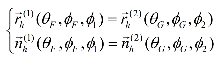
Where, the subscript “h” indicates that each vector is located in the meshing coordinate system sh; θ F, Φ F and θ G, Φ G is the surface coordinate parameters of the pinion and the gear tooth surface respectively; Φ 1 and Φ 2 is the meshing angle of the small wheel and the big wheel respectively.
Since TCA technology assumes that the gear teeth are completely rigid and does not consider the effect of load, the meshing process of spiral bevel gear pair is described from the perspective of pure mathematics. Therefore, the analysis results are generally used to evaluate the tooth surface quality corresponding to the initial design parameters, which is very different from the actual load-bearing operation.
Load tooth contact analysis (LTCA) technology considers the influence of load deformation and load distribution on the meshing characteristics of spiral bevel gears during the actual work of spiral bevel gears. The LTCA basic equation based on TCA technology, finite element method, flexibility matrix method and mathematical programming method is:
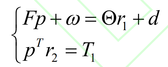
Where, f is the NxN flexibility matrix, and N is the total number of discrete points that may contact at the current meshing instant; P is the n-dimensional load vector; ω Dimension n initial gap vector; Θ Is the angle of the big wheel caused by elastic deformation; R1 and R2 are the turning radius vectors of the contact points of the n-dimensional small wheel and the large wheel respectively; D is the clearance vector after n-dimensional elastic deformation; T1 is the input torque.