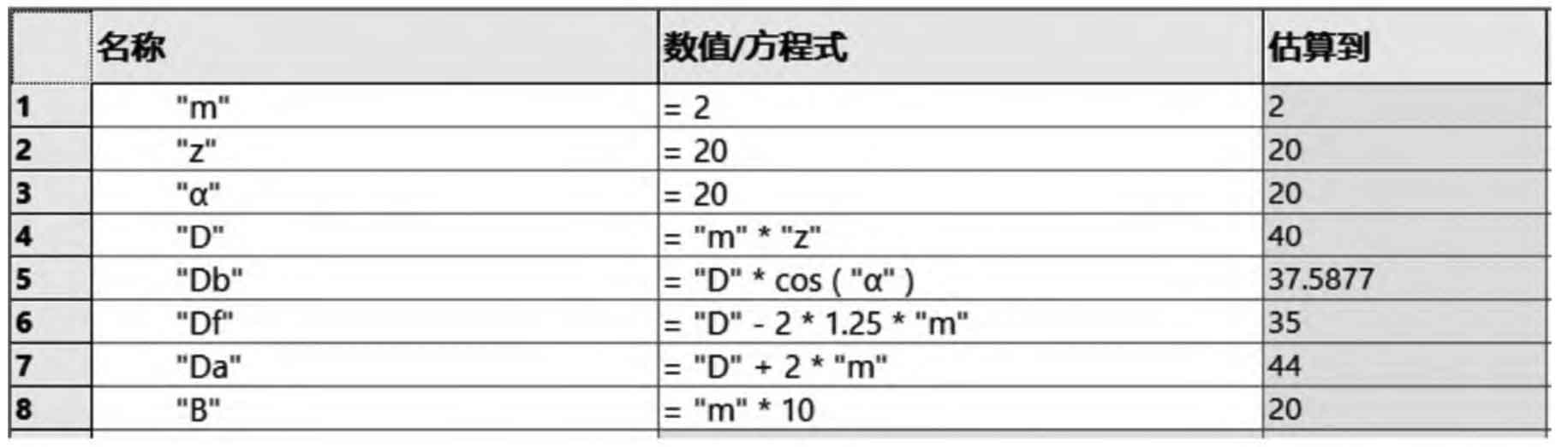
1. Create global variable equation
Click the command “Σ equation” in the “tools” menu of SolidWorks software, and use the global variable function to input the module m, number of teeth Z, indexing circle diameter D, base circle diameter dB, addendum circle diameter Da, root circle diameter DF and tooth width B in the global variable in turn. With modulus M = 2mm, pressure angle α= 20 °, number of teeth z = 20, c * = 0 25, h * a = 1 as an example, the Σ equation interface is shown in Figure 1.
2. Construction of involute
(1) Draw the root circle, base circle and graduation circle. Draw the tooth root circle in the sketch, input the dimension, select the global variable, and select DF; Draw the dividing circle, input the dimension, select the global variable, and select d; Draw the base circle, input the dimension, select the global variable, select dB, and add the equation “d” * cos (20) / 2 to the radius dimension of the base circle.
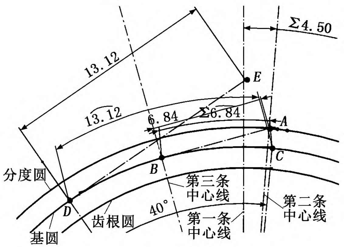
(2) Draw a secondary centerline. Draw three centerlines with the center o as the starting point. The first one is vertical, and the angle between the first and the second centerline is added with equation 360 / (“Z” × 4) Definition: the third and second definitions are 20 ° in the opposite direction. The intersection of the second centerline and the dividing circle is a, and the intersection of the third centerline and the base circle is B. the centerline connects point a and point B.
(3) Make any point C on the base circle, and mark the arc length of point C and point B, that is, the distance from point a to point B. Connect the origin and point C, and make an angle of 40 ° between the centerline and OC, and intersect with the base circle at point D. Make the centerline de perpendicular to OD through point D, and mark that the length of De is equal to the arc length of CD. The generating lines of point a and point E on the involute tooth profile are made through the constraint relationship.
(4) Get an involute tooth profile. Use the spline curve tool to connect the three points c, a and E, and this curve is the required involute, as shown in Figure 2.
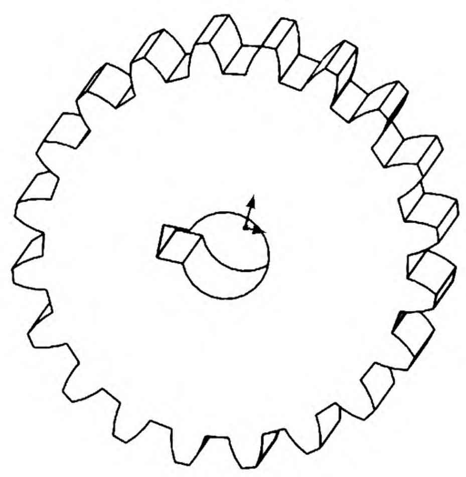
3. Gear Solid Modeling
Take the first centerline as the axis, mirror the involute and centerline OC, draw the addendum circle, and enter the dimension. After cutting, stretch the tooth thickness, array the teeth, and select the global variable Z for the number of teeth, and then draw the keyway stretch cut to complete the modeling, as shown in Figure 3.