
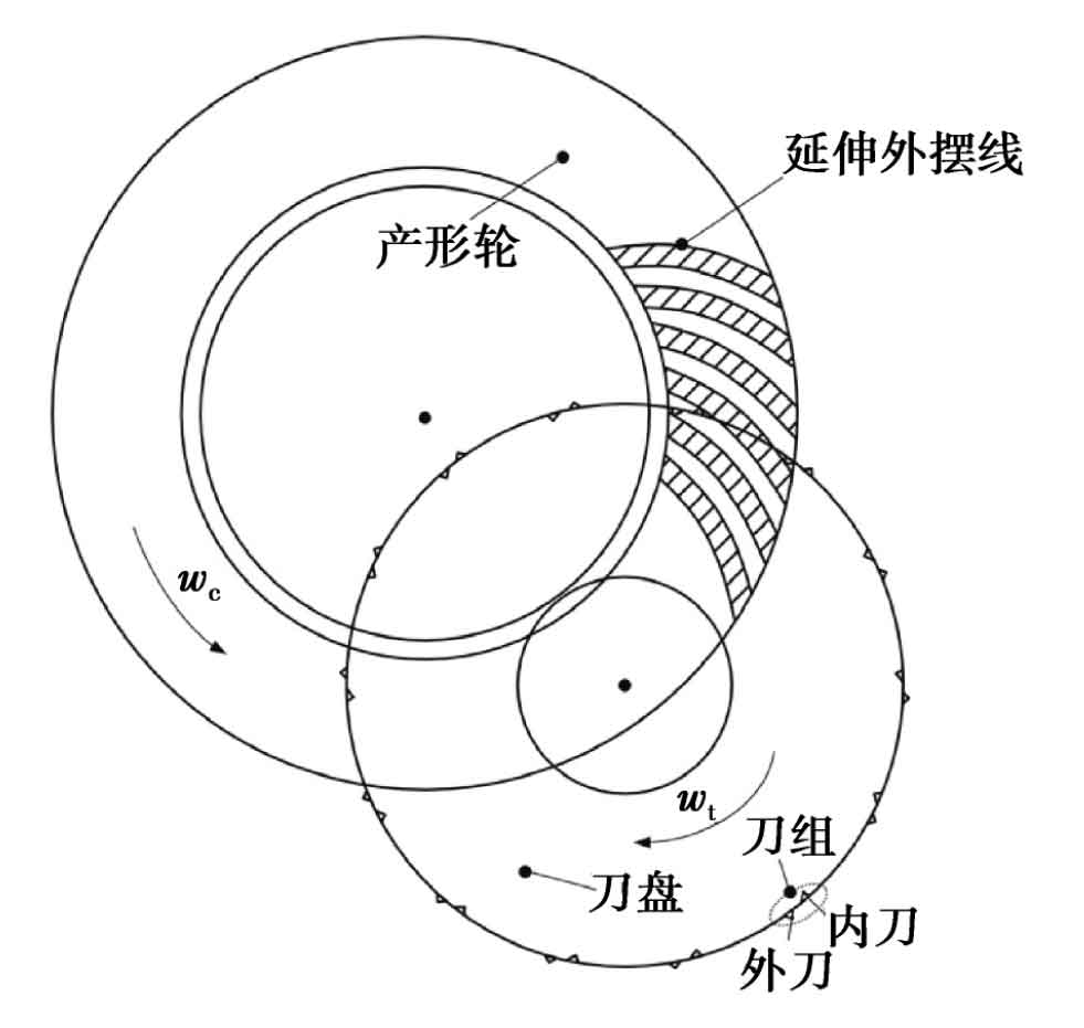
Oricon hypoid gears are machined by end face hobbing. Figure 1 shows the gear cutting principle of the end face hobbing of the hypoid gear made by Oricon. The cutter head rotates around the base circle while rotating to form an extended epicycloid tooth line. There are Z0 sets of cutter teeth on the end face cutter head, and each set of cutter teeth has at least one inner cutter and one outer cutter, which are used to process the convex and concave surfaces of the gear teeth respectively. WC and WT are the angular velocity of the generating wheel and the cutter head respectively. The generating wheel is composed of the cutting rotary surface of the cutting edge of the tool in the machine coordinate system.
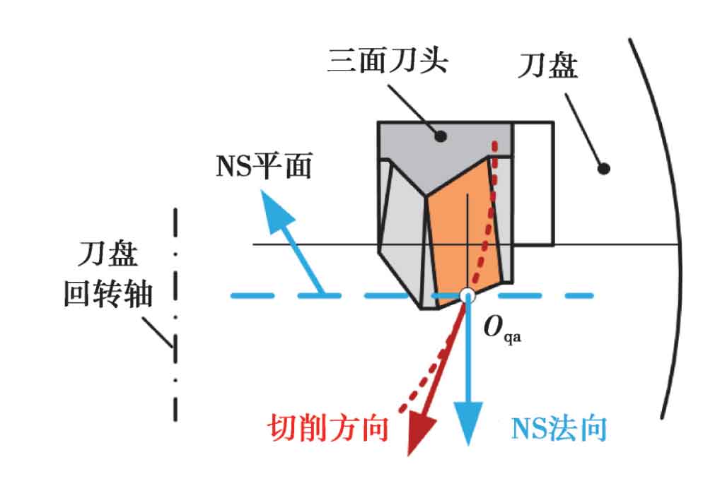
The modeling datum of hypoid gear is generally divided into two kinds: cutting direction datum and NS normal datum. NS normal datum is established in the normal direction of NS plane, and cutting direction datum is established in the tangent direction of cutting curve, as shown in Figure 2. Figure 3 is a cross-sectional view of the cutting edge of the Oricon tool, which is composed of the main cutting edge and the tip arc segment.
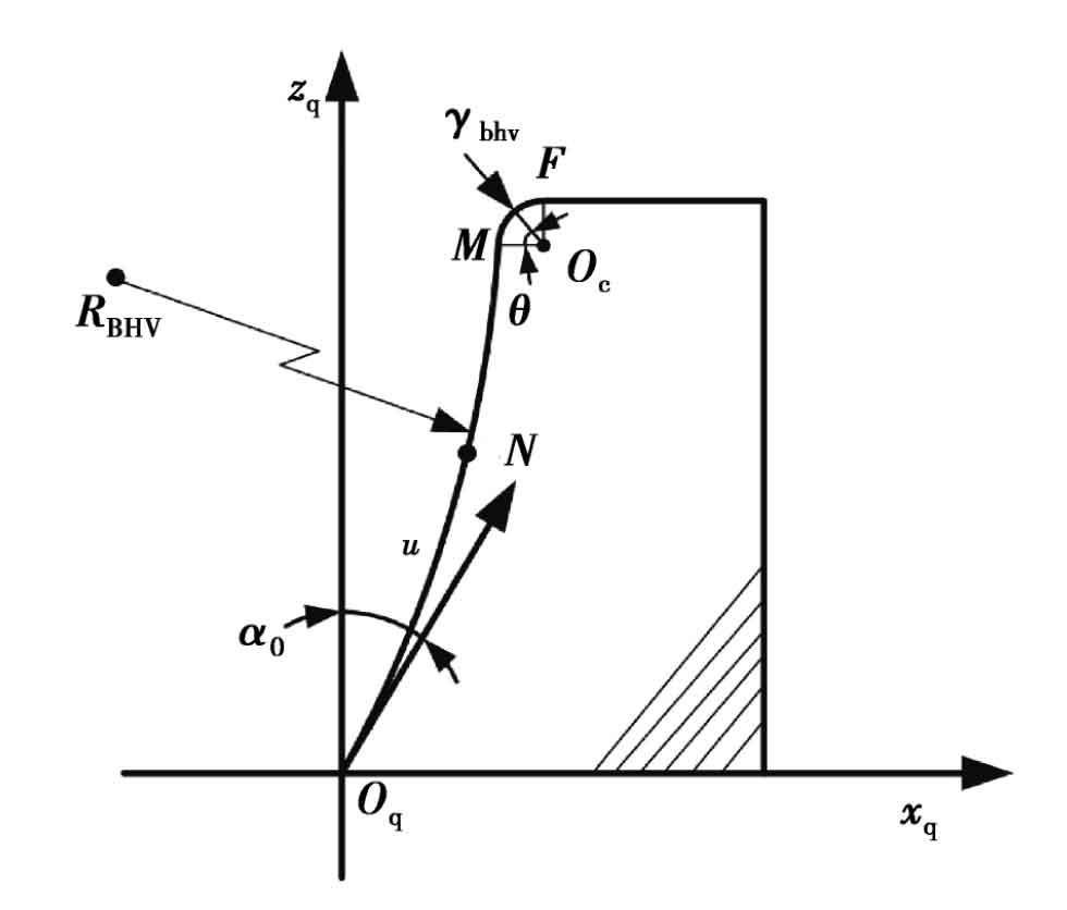
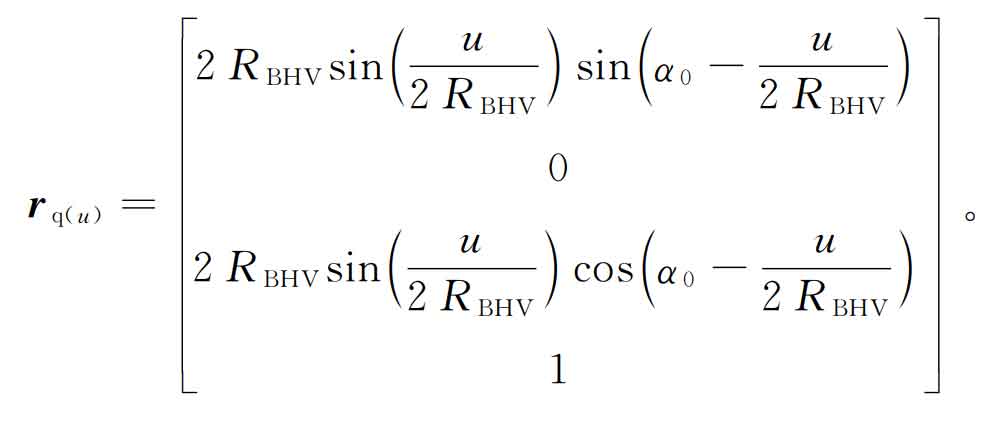
Taking the left chord internal cutter as an example, under the coordinate system sq (XQ, YQ, ZQ), the mathematical model of the main cutting edge and the tip arc segment is established, and its expression is as follows: the main cutting edge (oq-m segment):
Tool tip arc (M-F segment):
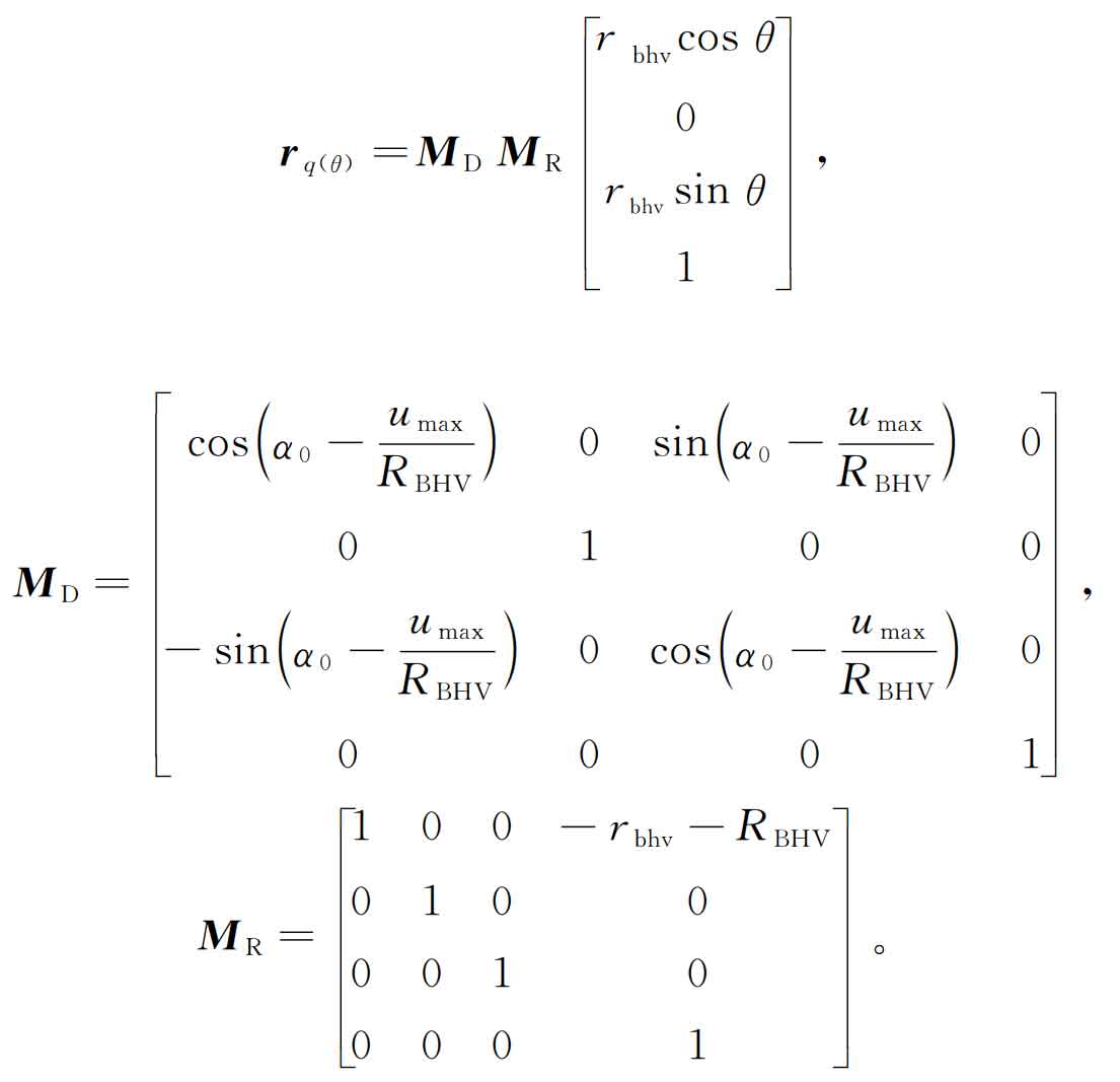
In the figure, OQ is the tool reference point, OC is the center of the tip arc segment, and M is the common tangent point between the tip arc and the main cutting edge. α 0 is the pressure angle of the reference point, u is the arc length from the reference point of the cutting edge to any point n of the main cutting edge, Umax is the arc length from point m to the reference point, rbhv is the arc radius of the main cutting edge, rbhv is the arc radius of the tool tip, θ Is the angle of the tip arc segment. The matrix MD and MR are the transformation matrix from the tool tip arc segment to the coordinate system sq (XQ, YQ, ZQ).
Figure 4 shows the trihedral cutter (a) and cutter head model (b) for machining Oricon gears. The coordinate system sq (XQ, YQ, ZQ) is established on the tool reference point of the rake face, St (XT, YT, ZT) is the cutter head rotation coordinate system, and SA, Sn, SS and SG are auxiliary coordinate systems. Among them, Sn (xn, YN, Zn), SS (XS, ys, ZS) coordinate systems are the cutter head cutting direction datum and NS plane datum coordinate system respectively, and the included angle between ns normal datum and cutting direction datum is γ s。
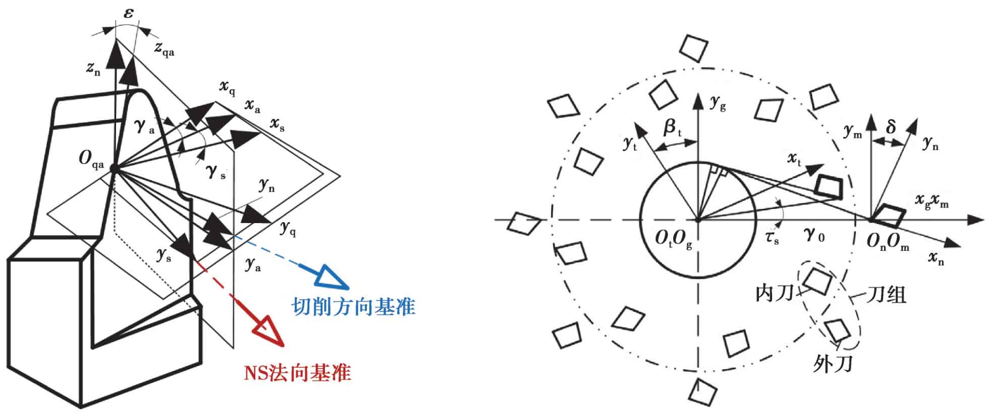
(a)Trihedral cutter (b)Cutter head
The included angle between the reference point of the cutting edge of the cutting inner tool and the outer tool is s. The cutting edge obtains the cutting path surface in the st (XT, YT, ZT) coordinate system through the coordinate transformation of the cutter head. RT (U) main cutting edge segment, RT( θ) Is the arc segment of the tool tip, and its expression is:
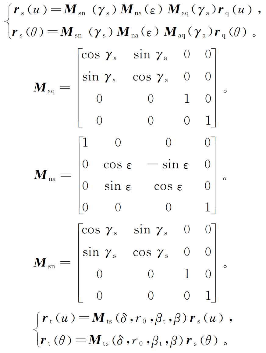
Where: γ A is the rake angle of the tool; ε Is the tool regrinding angle; δ Is the cutter tooth direction angle; Ro is the turning radius of the tool reference point; β T is the initial installation angle of the tool. MAQ, MNA, MSN and MTs are the transformation matrix of tool rake angle, regrinding angle, main edge back angle and cutter head coordinate system respectively. MSN is the NS normal reference coordinate transformation matrix, and MNA is the cutting direction reference coordinate transformation matrix.