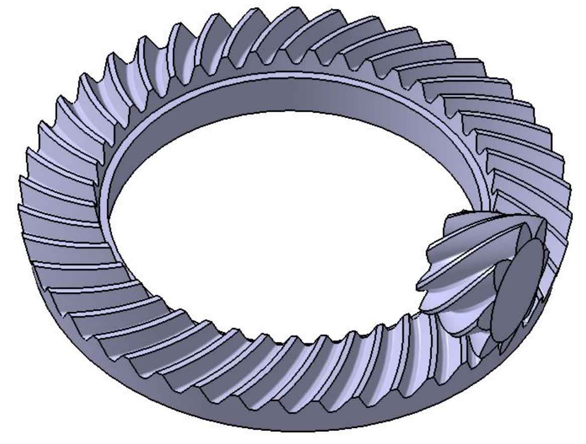
Import the hypoid gear coordinates into CATIA, use the surface function to get the gear surface of the hypoid gear, and finally get the three-dimensional solid model of the hypoid gear according to the gear blank parameters, as shown in Figure 1.
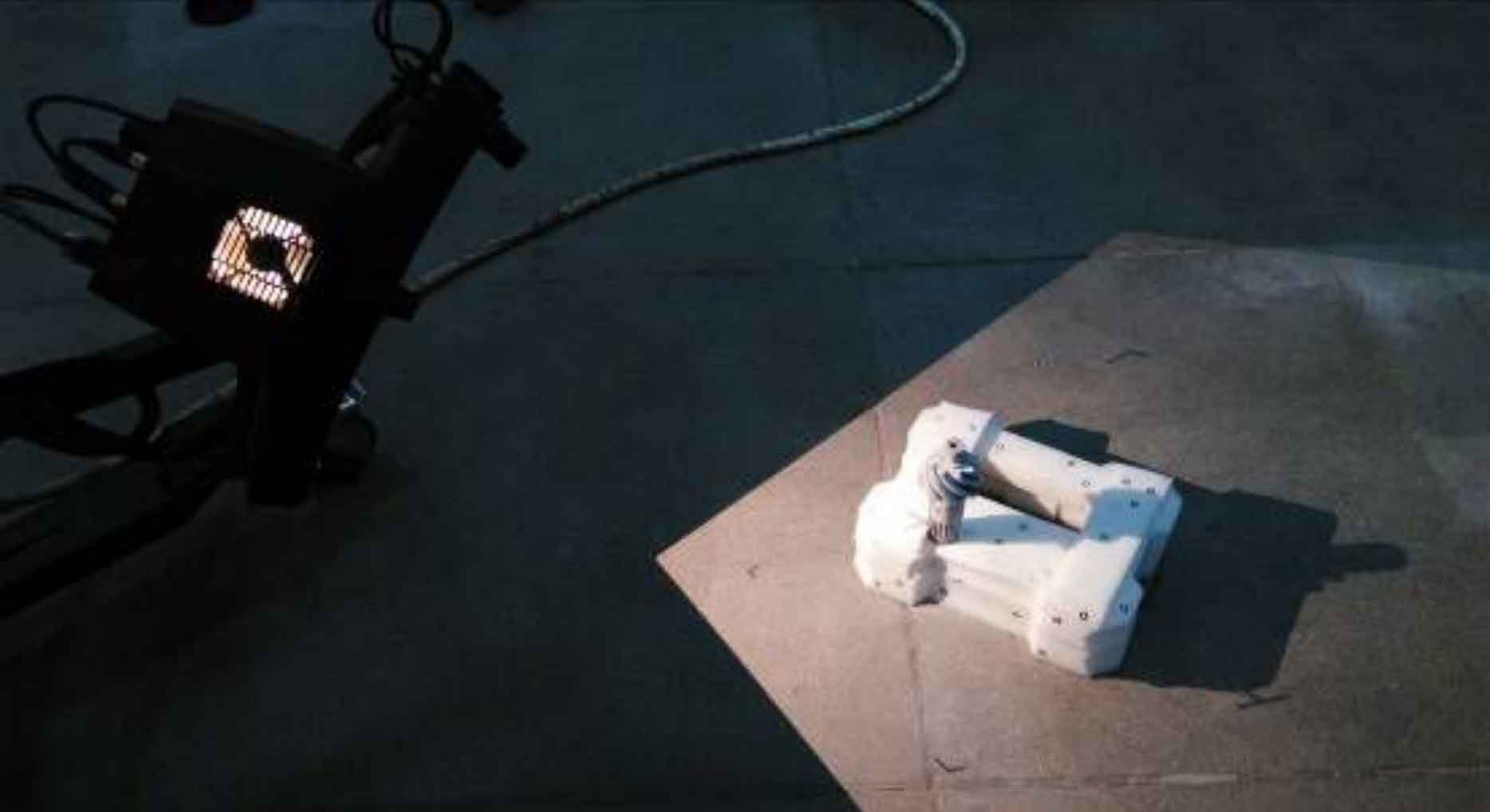
In order to compare the gap between the established three-dimensional solid model and the actual machining of hypoid gears, the German three-dimensional optical measurement system ATOS II is used to align hypoid gears for three-dimensional scanning measurement, as shown in Figure 2, in order to obtain the three-dimensional point cloud information of hypoid gears.
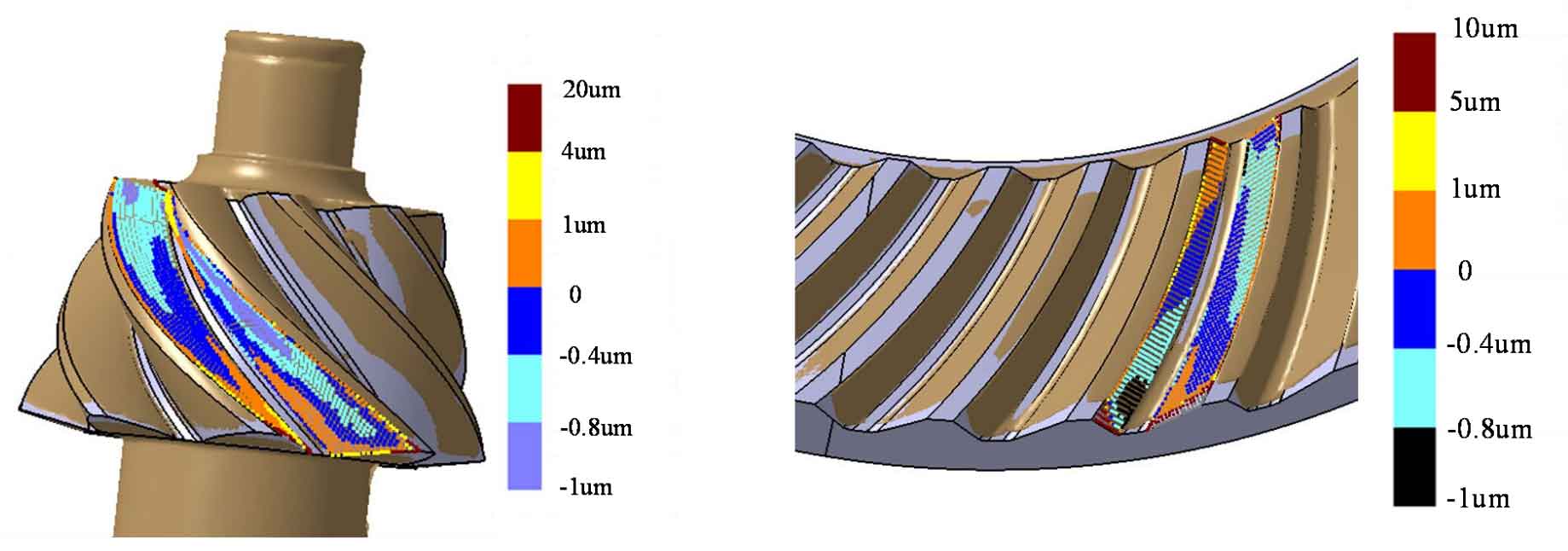
Comparing the established three-dimensional model with the measured point cloud, as shown in Figure 3 (a) and (b), the tooth surface deviation of pinion and gear can be seen that the established tooth profile is basically consistent with the actual machining tooth profile. Except that the local length of the edge is larger than the theoretical one, the tooth surface deviation is within 0.02mm, which may be caused by the deviation of hypoid gear during the machining process and measurement, However, these deviations are within the allowable range of the design. The comparison results show that the quasi Bi surface 3D model is correct.