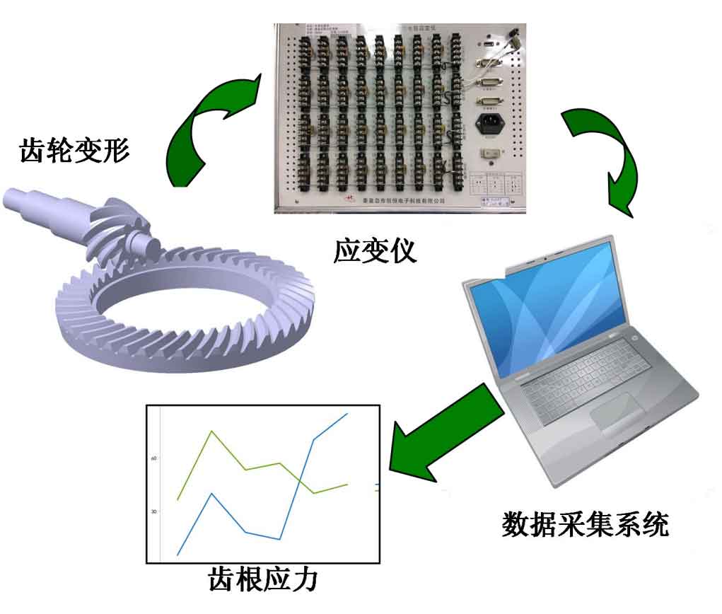
In order to verify the accuracy of the established finite element model, the tooth root bending stress in the meshing process of hypoid gear in the drive axle is measured. This paper is based on the meshing process of the driving and passive gears of the integral drive axle. In the meshing process of the hypoid gears, the speed has little effect on the bending stress of the gear root, and it is very difficult to dynamically measure the bending stress of the gear root when the slip ring is arranged in the integral drive axle. Therefore, this paper is based on the measurement of the bending stress of the gear root when the integral drive axle is in the static meshing of the hypoid gears. Using the test principle of gear stress as shown in Figure 1, the tooth root position will be deformed during gear meshing. Firstly, the strain value of the resistance strain gauge at the tooth root position is obtained by using the strain gauge and the data acquisition system, and finally the tooth root stress is obtained by the data acquisition system.
The following points should be paid attention to when measuring stress: first, it is necessary to select a strain gauge with appropriate grid length. Because the space of the root of the hypoid gear is narrow, the grid length is too long, which is easy to enter the meshing area of the hypoid gear, resulting in the damage of the strain gauge. The grid length is too small, which makes it inconvenient to paste the strain gauge. Second, insulation treatment should be done between the connecting wire of the strain gauge and the gear blank. Third, choose appropriate strain testing instruments, data acquisition system and stable test bench.
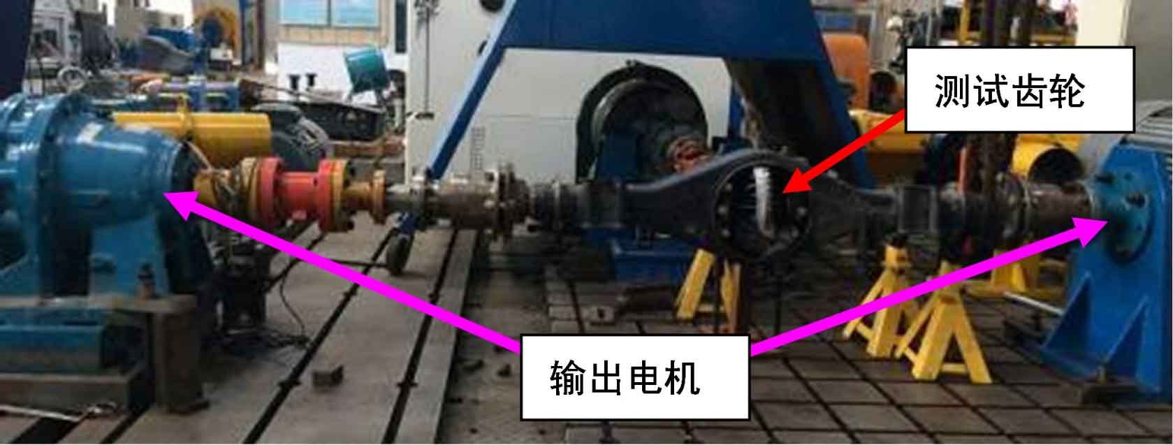
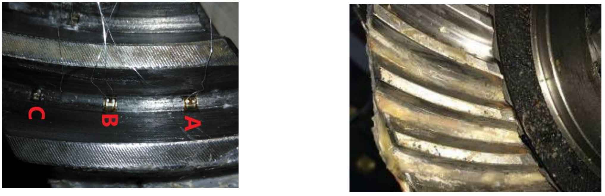
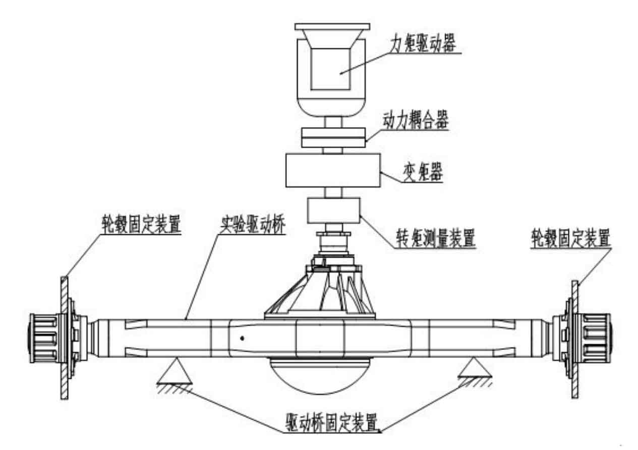
According to the size of hypoid gear, bv120-1aa resistance strain gauge, cm-2b static strain measurement and analysis system, and the automotive electronic control power train test bench produced by Burkee company of the United States are selected. The structure of the test bench is shown in Figure 2, and the specific test device structure of the bench is shown in Figure 3. During the test, the hub was fixed. In order to compare with the predicted results, 900nm input torque was loaded on the input end of the drive axle, and the resistance change of the strain gauge was converted into a current signal by using the static strain gauge. According to the relationship between the current change and the strain, the deformation of the tooth root during the meshing of the hypoid gear was obtained and output to the computer through the USB interface of the strain gauge. The position of strain measuring points should be located at the dangerous section of hypoid gear root, as shown in Figure 4 (a). Three measuring points are arranged at the root of a single tooth, and the effect of strain gauge packaging is shown in Figure 4 (b).