
An important goal of hypoid gear design is to optimize the performance of gear pair installation deviation. By measuring the contact position of the big and small gears, it can be found that the deformation of the hypoid gear support of the drive axle will affect the gear meshing footprint. During the assembly of the drive axle hypoid gear, special equipment is used to test the meshing footprint of the gear when it is unloaded, and the meshing position between the gear teeth can be changed by adjusting the relative position between the gears. However, in the design process, the influence of gear installation deviation on the bending stress of gear root is less, and the loss of customers caused by the bending fracture of tooth root of hypoid gear in the process of use is much more serious than the gear contact problem. The theoretical meshing footprint of hypoid gears can be obtained by analytical method, and the bending deformation of gear root is affected not only by the deformation of gear teeth, but also by the deformation of gear blank, which is difficult to be expressed by simple analytical method. Therefore, next, based on ABAQUS finite element method, the influence of installation deviation on tooth root bending stress during gear meshing will be studied. From the analysis in the previous section, it can be seen that the change of tooth root bending stress during gear meshing is mainly related to the first principal stress and the third principal stress. The third principal stress represents the compressive stress on the gear, the first principal stress represents the tensile stress on the gear material, and the tensile stress is more likely to cause the damage of the gear tooth root. Therefore, this section mainly analyzes the influence of installation deviation on the maximum tensile stress corresponding to the bending stress on the gear tooth root. In order to compare the influence of different installation deviations of gears on the bending stress of the tooth root, only the hypoid meshing gear pair is analyzed separately below.
The finite element modeling process of meshing analysis of hypoid gear pair is similar to that of integral drive axle. The difference is that in the contact analysis step, only the degrees of freedom in all directions of the joint between the big gear and the main reducer housing are constrained, and the rotation angle is applied to the pinion; In the loading analysis step, the boundary condition of the pinion is the same as that of the contact analysis step, and the load is loaded on the gear; In the rotation analysis step, the pinion applies a rotation angle, and the boundary conditions of the pinion are the same as those in the previous step.
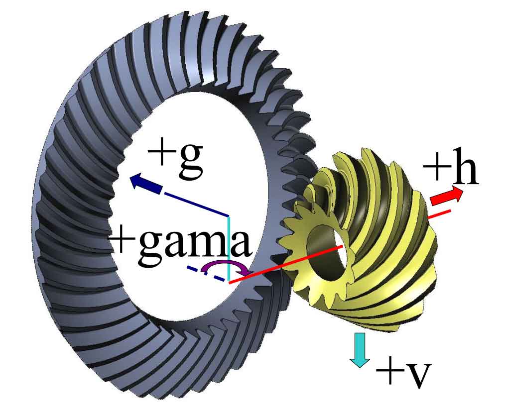
The typical installation deviations of hypoid gears are mainly divided into four categories, namely, the axial installation deviation g of large gears, the axial installation deviation h of small gears, the installation deviation V of the offset distance of large and small gears, and the installation deviation Gama of the cross angle between the axes of large and small gears. The corresponding direction definitions are shown in Figure 4.9. The ideal installation position of gears is that all installation deviations are equal to zero (v=h=g=gama=0). In this paper, using the method of controlling a single variable, only one of the installation deviation variables changes during each test, while the other deviations are equal to zero, such as h=g=gama=0 when v=0.1mm, and so on. Because the designed maximum output torque of this gear is 1596nm, it is most likely to cause bending fatigue damage to the gear root at this time. Therefore, in the simulation process, the resistance torque applied by the big gear is 9000nm, and the corresponding rotation angle is applied on the small gear.