
1.Analysis type
First, the static nonlinear meshing analysis is carried out. In the analysis step, the class’ static stress / displacement analysis’ is analyzed. In this type of analysis, the influence of component inertia is ignored. At the same time, some time-varying factors such as fatigue fracture, crack propagation and viscoelasticity of hypoid gears are also ignored. The static analysis can be linear or non-linear, which essentially affects the method of establishing boundary conditions in the analysis step. The drive axle hypoid meshing gear pair established in this paper has nonlinear behaviors such as hypoid gear contact nonlinearity and large displacement geometric nonlinearity, so the nonlinearity must be opened in the modeling process.
2.Contact properties
In the static gear meshing analysis, two analysis steps are defined: contact analysis step and rotation analysis step. In the contact analysis step, the load is applied to the driven gear in the form of ramp function. In the rotation analysis step, the load is applied instantaneously. The rotation angle of the hypoid gear should be set to be greater than the rotation angle of one tooth, so as to obtain the complete meshing process of the hypoid gear from meshing to meshing.
After the finite element model of hypoid gear successfully defines the analysis step, it is necessary to establish the interaction relationship between teeth. The type of contact between the interaction tooth surfaces is defined, which is set as limited slip and surface to surface contact in the simulation. The contact tooth surface of the contact driving gear and the contact driven gear is defined as the master surface and the slave surface in the contact attribute. The contact attribute of hypoid gear is defined as “hard” contact in the normal behavior, and the friction coefficient is defined as 0.1 in the tangential behavior. After the contact attribute is defined in the model, these attributes can be simply transferred to the subsequent analysis step.
3.Boundary conditions
In the contact analysis step, the degrees of freedom in all directions of the nodes at the connection between the large gear and the differential case are limited, and the degrees of freedom in other directions except the axis are limited at the installation position nodes of the pinion and the bearing inner ring, and a small rotation angle is applied at the coupling node of the pinion spline position. In the loading analysis step, the freedom of the large gear in the axial direction is released, and the resistance torque is applied in the axial direction, while the small gear applies the rotation angle in the axial direction. Other settings are the same as those in the previous analysis step.
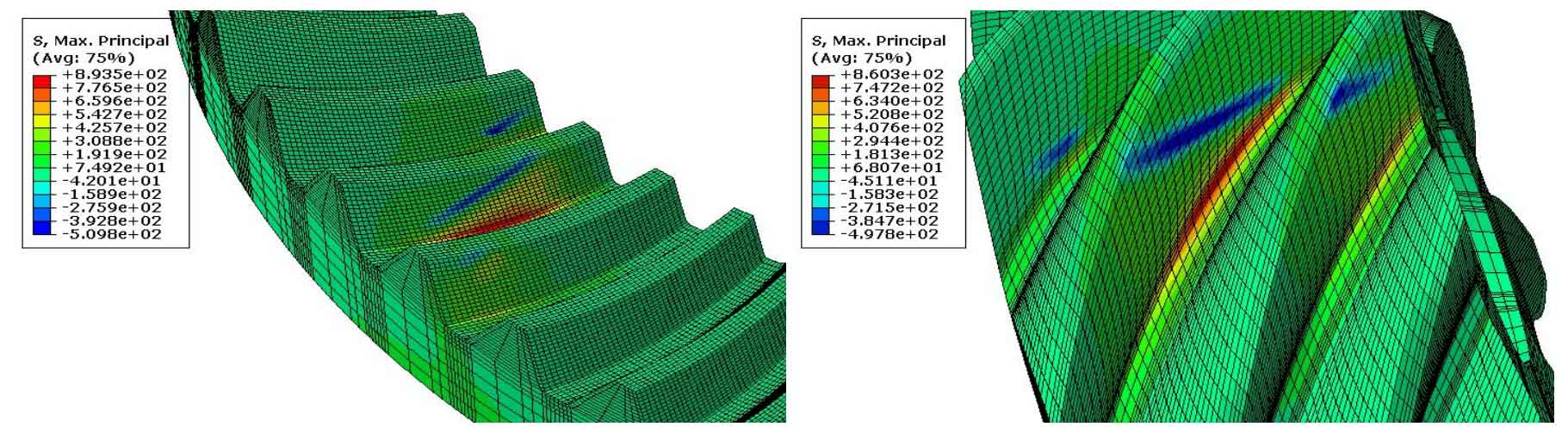
The meshing model of the hypoid gear of the drive axle is established according to the above method. When the drive axle is dragging forward, that is, when the concave surface of the driving gear drives the convex surface of the driven gear, the maximum principal stress distribution diagram of the hypoid gear at a certain meshing moment is as shown in the figure. It can be seen that the maximum stress is located at the gear tooth position in the intermediate meshing. The theoretical meshing of hypoid gears is point contact. However, due to the elastic deformation of the tooth surface, the meshing position of hypoid gears is close to ellipse. The classical hypoid gear contact theory [9] can also prove this. At this time, there are 3 pairs of gear pairs participating in meshing, and the overlap coefficient between hypoid gear pairs is greater than 1. It shows that hypoid gear can transmit torque more smoothly than spur involute gear.