
According to the meshing stiffness calculation model of hypoid gears, it is necessary to calculate the transmission error of hypoid gears without load before calculating the meshing stiffness of hypoid gears under load. Based on the finite element model, a small load is applied when calculating the transmission error without load. The reason for applying small rotational torque is that most of the current meshing analysis models are based on the geometric meshing relationship of hypoid gears. At this time, the load torque of hypoid gears is not considered, and no force should be applied during the contact analysis of hypoid gears. However, when the finite element method is used to analyze the contact of hypoid gears, a force needs to be applied to keep the hypoid gears in contact. This torque can be very small. Here, it is taken as one percent of the torque applied by the hypoid gear during normal operation. Under the action of this small moment, the finite element contact analysis can basically simulate the contact process of the hypoid gear under no load, which can ensure that there is only one pair of teeth in contact during the finite element analysis, and can approximate the transmission error of the hypoid gear under no load.
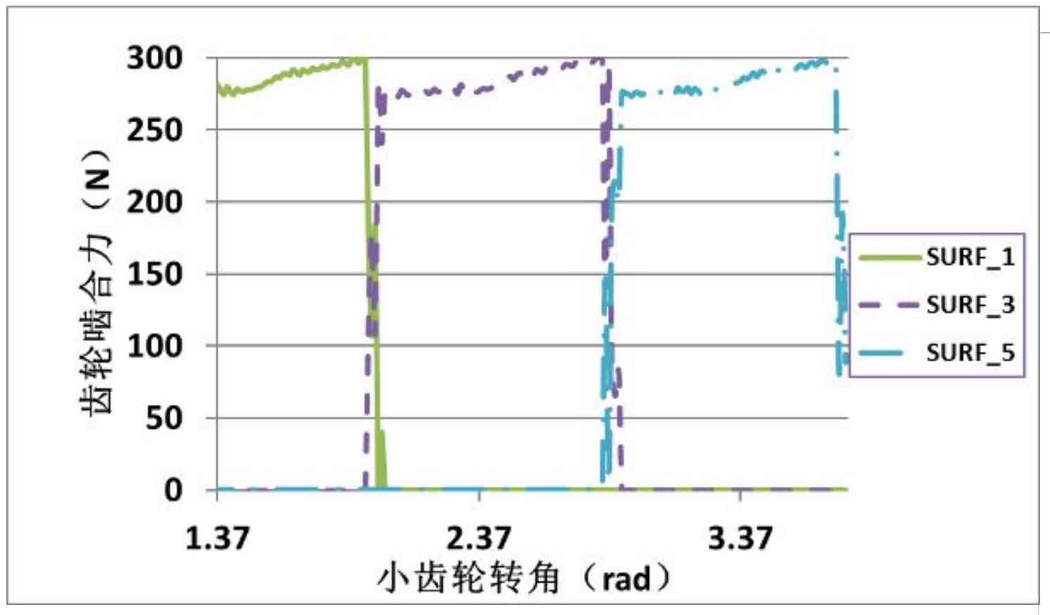
Apply 10nm resistance torque to the output end of the large wheel of the hypoid gear. As shown in Figure 1, it is the meshing force generated in the normal direction at the meshing point of the hypoid gear during the rotation of the hypoid gear. The change history of the meshing force in the normal direction at the equivalent meshing point of the contact surface of the three pairs of meshing teeth is expressed as suf_ i. Where I = 1,3,5 represents the tooth surface of large gear, I = 2,4,6 represents the tooth surface of small gear and suf of large gear_ 1 and pinion suf_ 2 is the meshing tooth pair, and so on. The normal force on the tooth surface of large and small gears is the force and reaction force, so this paper only gives the force on the tooth surface of large gears. It can be seen from the figure that the normal meshing force of each tooth does not overlap, and the hypoid gear is always in the single tooth meshing state, and the meshing force value is small at this time.
The transmission error in the meshing process of hypoid gears can be obtained by post-processing the meshing analysis results of large and small gears, as shown in Fig. 2. It can be seen from the figure that the transmission error of hypoid gears under small load is approximately parabola, which is consistent with the actual transmission error of hypoid gears under small load measured by the test. This is to reduce the contact impact of hypoid gears in the meshing process, In the design of hypoid gear, the transmission error of hypoid gear without load is designed as parabola. At the same time, it can be seen that there is a large fluctuation between adjacent meshing points of small load transmission error, which is caused by the unstable contact of hypoid gears when the load is small.