
ZHY gear provided the part drawing and assembly drawing of the hypoid gear of the main reducer of a certain vehicle. According to the design requirements of the drawing, the tooth ratio of the gear is 8 / 41. The three-dimensional solid model of the hypoid gear is established in Pro / E, in which the driving wheel is a left-hand gear and the driven wheel is a right-hand gear. Then the assembly and interference analysis are carried out in the Pro / E Assembly module to provide an accurate model for the following analysis.
(1) According to the part drawing of the driven wheel, create the basic curve and the basic circle, including the root circle, the tooth top circle and the graduation circle. First create the datum plane, and then create the basic circles at the large end and the small end in the datum plane, as shown in Figure 1.
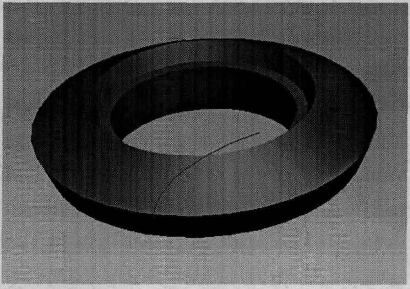
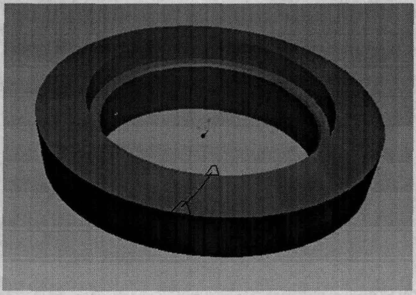
(2) According to the dimensions given in the drawing, create the wheel blank section of the driven wheel, and then rotate the section around the central axis (Y axis) once to obtain the wheel blank of the driven wheel, as shown in Fig. 2.
(3) Create an involute at the big end of the driven wheel. Establish the local coordinate system, insert the curve, and generate the involute on the local coordinate system according to the parameter equation of the involute, wherein the equation of the involute is:
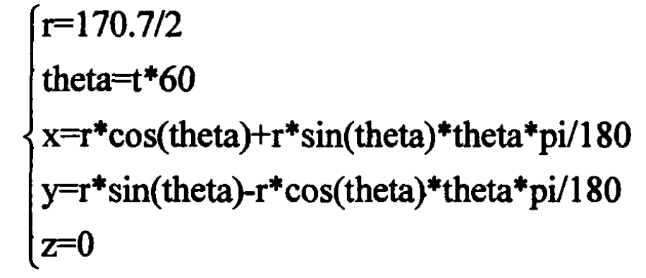
Where the independent variable t will generate a complete involute for X, y and Z (which will change from 0 to 1), as shown in Fig. 3.
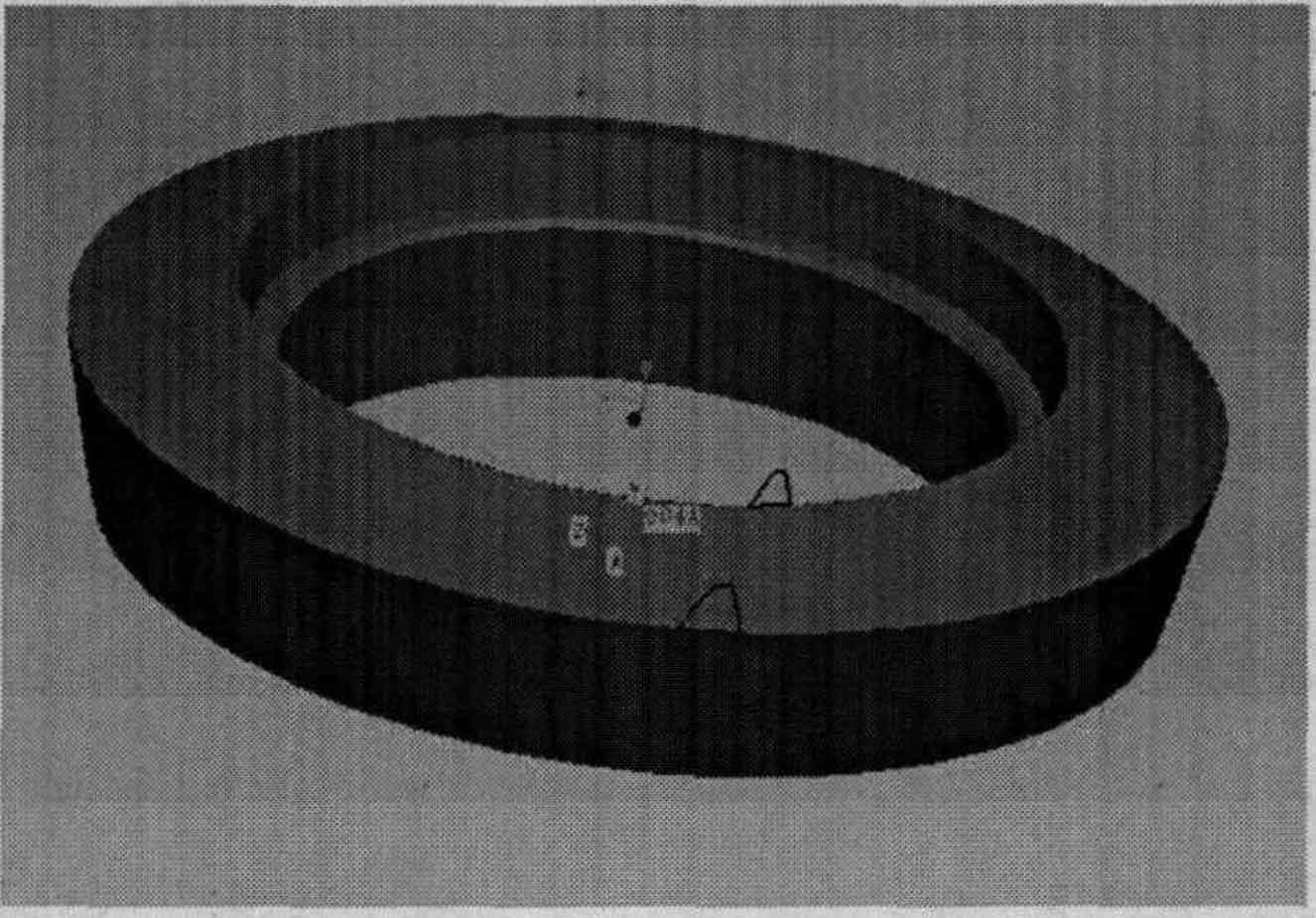
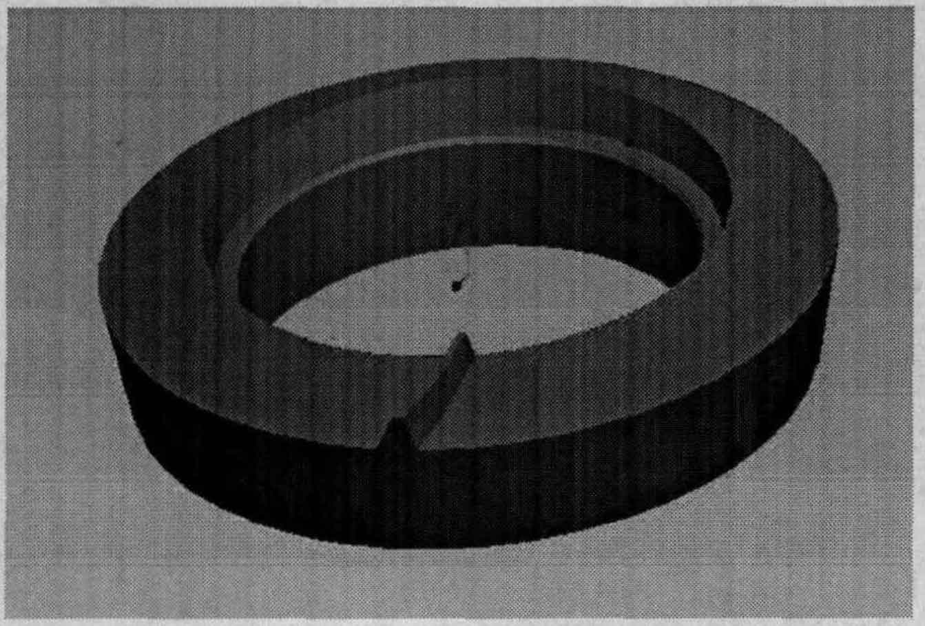
(4) According to the same method, generate the involute at the small end of the driven wheel, and mirror the two involutes. According to the basic circle and involute of the gear, create the tooth profile sections of the big end and the small end respectively, and then rotate the small end section around the central axis to obtain the model shown in Fig. 4.
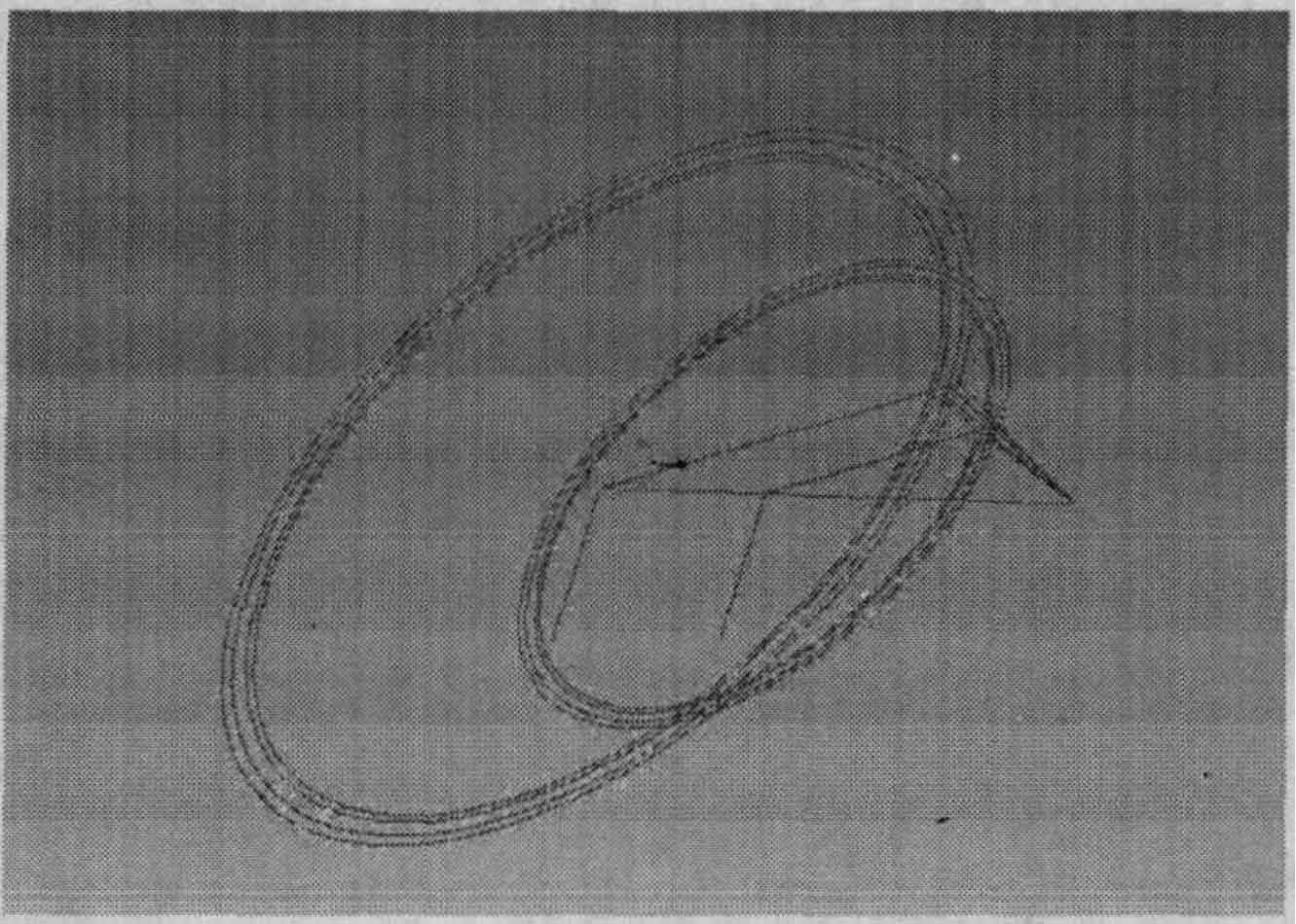
(5) Create a sweep track line. The tool path is generated according to the diameter of the milling cutter head d = 170.6 and the spiral angle of the center point 26.77 °, and the tool path is projected onto the indexing circle surface. The completed scanning path line is shown in Fig. 5.
(6) Create a sweep blend section. According to the method of scanning and mixing, select two sections respectively and ensure the consistency of the direction. According to the scanning track line, complete the creation of the first gear tooth. The completed features are shown in Fig. 6.
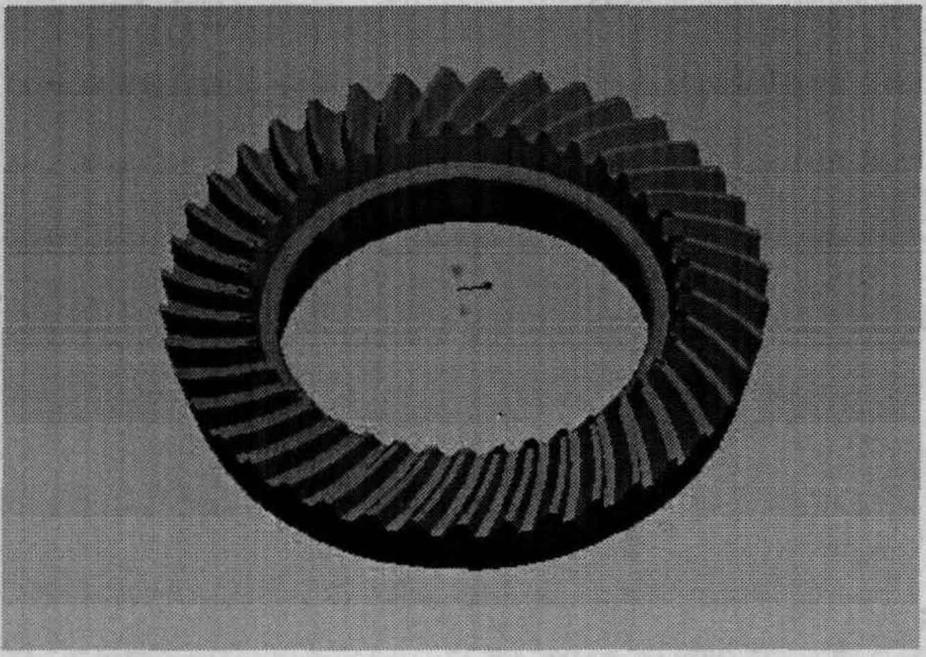
(7) The first gear tooth is arranged in a circular array, with the number of 41 and the angle of (360 / 41) °, and a complete three-dimensional solid model of the driven wheel is obtained. Then chamfer it, and finally complete the screw hole, thread and other features according to the part drawing. The completed driven wheel model is shown in Fig. 7.
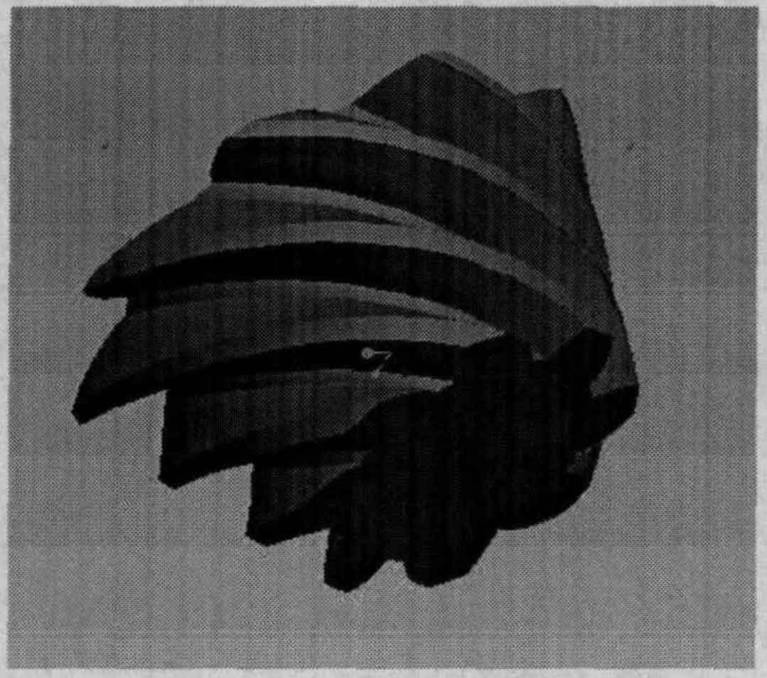
Using the same method, create the 3D solid model of the driving wheel according to the part drawing of the driving wheel, as shown in Figure 8.
According to the design drawings, the creation steps of hypoid gear are introduced in detail, and the creation of hypoid gear is completed, which is consistent with the actual model and lays a foundation for analysis.