
In order to reduce the transmission error below 1, the modification amount of helical gear is analyzed.
First, analyze the load per unit length of the tooth surface of the first stage helical gear 1 (i.e., contact spot analysis). The tooth width direction refers to the overlapping tooth width of the helical gear pair (the overlapping tooth width of the first stage reduction helical gear pair is 34). Set the horizontal axis coordinate as the rotation angle from the meshing start point to the end point, the vertical axis as the tooth width, the middle of the overlapping tooth width is 0, the left side is negative, and the right side is positive; The vertical axis refers to the load per unit area, which refers to the load distribution on the bearing tooth surface during the meshing process. The specific modification is shown in Fig. 1 and Fig. 2.
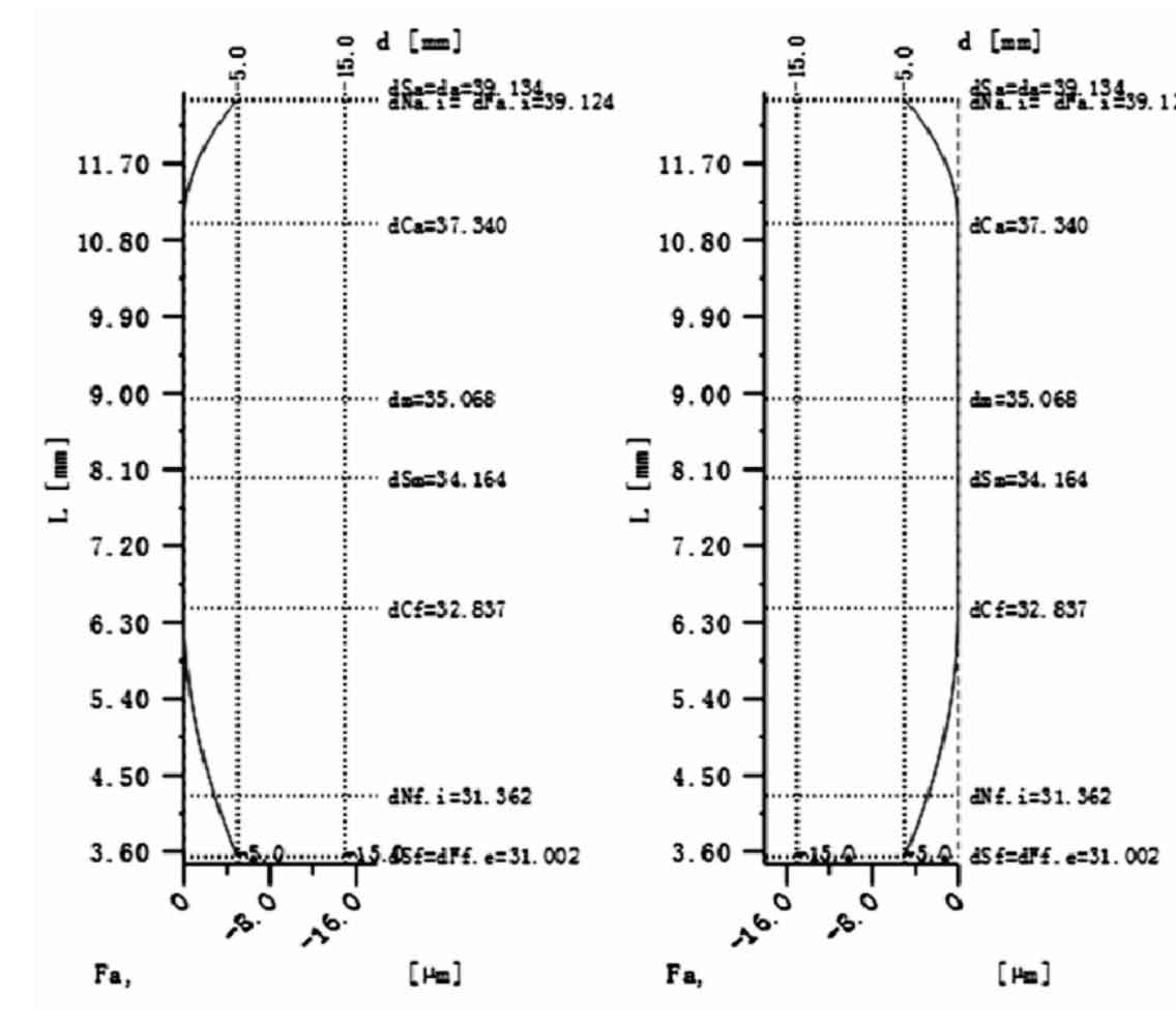
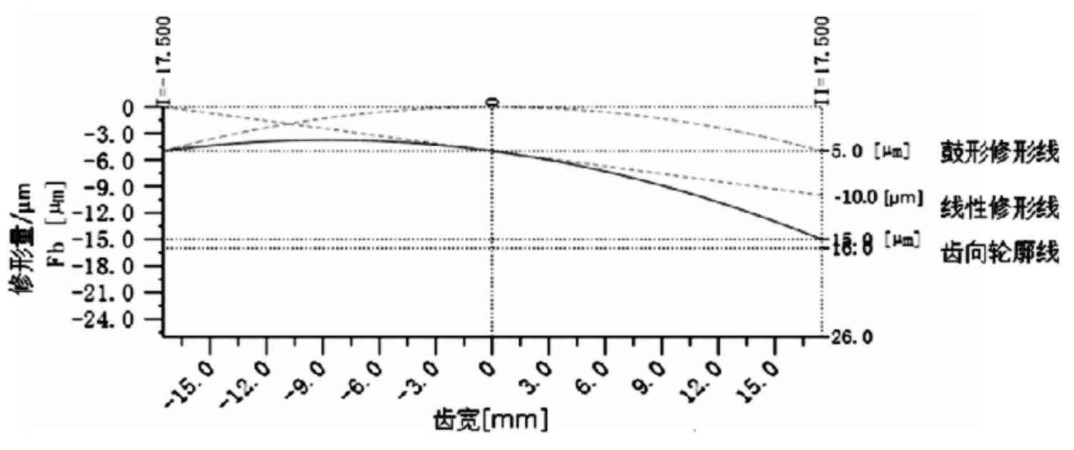
In this modification, the modification method and modification amount of the two helical gears are the same, and the modification of the left and right tooth surfaces is also the same. The tooth profile modification adopts linear modification and drum modification. The linear modification starts from the leftmost end and the right end is 10 μ m。 The modification parameter of drum shape is 5 μ m. Modification of the final tooth direction, the leftmost end is – 5 μ m. The rightmost end is – 15 μ m。 The tooth profile is modified by circular arc with a modification amount of 5 μ m。
After the helical gear modification is completed, the contact spots of the driving gear of the first stage reduction are analyzed. The maximum load per unit area after the modification is 1260n / mm2, and the maximum load before the modification is, which is reduced by nearly. The entire tooth width direction is evenly distributed, and the bearing capacity of the helical gear is improved.
Analyze the delivery error of the modified helical gear. As shown in Figure 3, the maximum value of displacement along the meshing line is 14.1, and the minimum value is 13.6. The absolute value of displacement becomes smaller, and the difference of displacement is 0.5 μ m. That is, the transmission error is reduced from 2.4976 μ M decreased to 0.5 (as shown in the table), reaching less than 1 μ M U.M.
| Load per unit area of tooth surface (n / mm ^ 2) | Transfer error/ μ m | |
| Before modification | 1741.6111 | 2.4294 |
| After modification | 1269.5111 | 0.5 |
According to the vibration theory, the response is the result of the excitation acting on the system. On the premise of not changing the overall structure of the system, the excitation can be effectively reduced and a better response can be obtained. Therefore, theoretically, the howling of the reducer after the modification can be effectively controlled.