
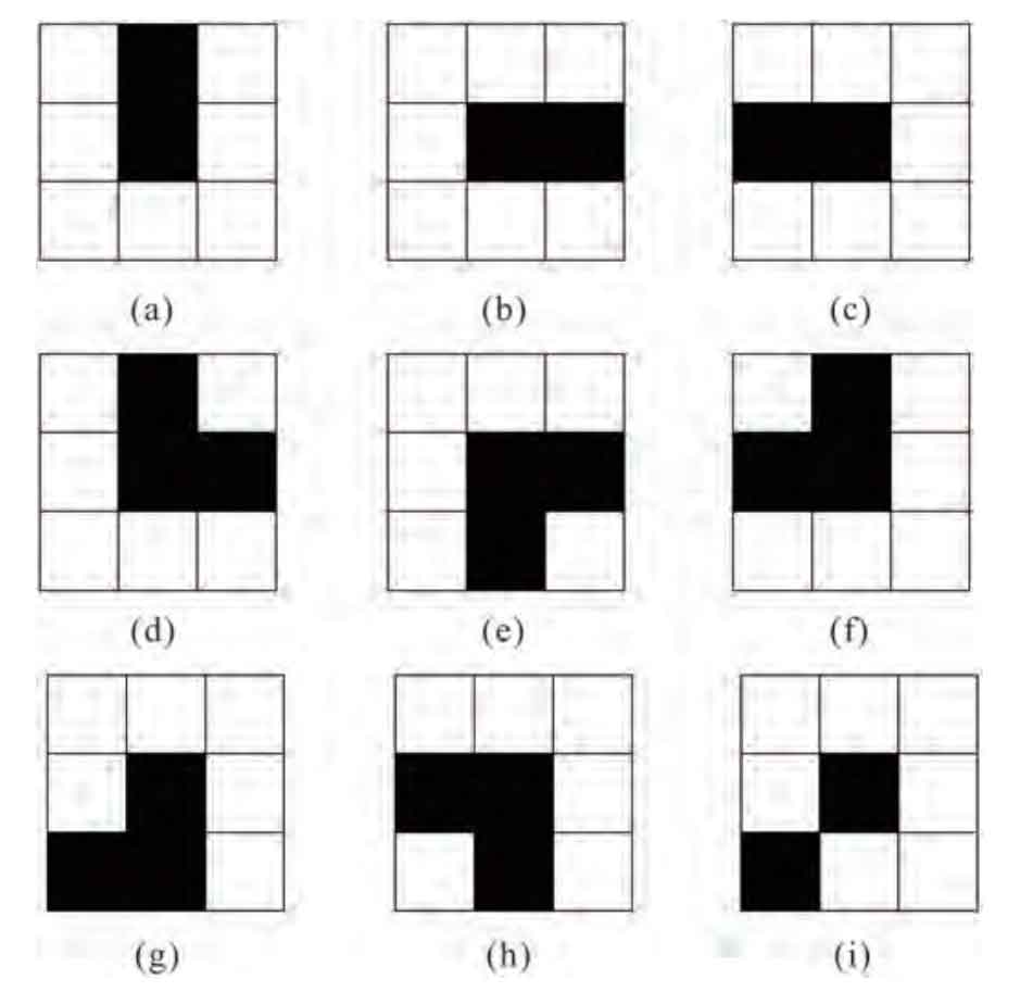
When designing the measuring process of the processing parameters of the cylindrical helical gear, firstly, the edge closure of the image considering the manufacturing error is detected. The pixel level edge detection algorithm needs to obtain the sub-pixel level edge position within a certain range in the image. For cylindrical helical gears, if the tooth profile detection is relatively accurate, the tooth profile presented at this time should be complete and continuous, and two closed contours can be clearly seen. In this process, we need to use the breakpoint detection template to detect it. Several common templates are shown in the figure.
Before the operation, the pseudo edge existing in the effect image of the edge detection operator is also a kind of outlier group. In the actual measurement process, it is necessary to eliminate the isolated outlier parameter group of the image edge. Different parameters have different measurement processes. For the measurement of the tooth pitch of the cylindrical helical gear, first place the cylindrical helical gear to be measured on the operating platform, place the measuring head about 10mm above the tooth top of the cylindrical helical gear and adjust it. The cylindrical helical gear needs to be fixed and clamped by the clamp.
Record the current position coordinate on the PC and mark it as “1”, select the measurement model, input the measured parameters of the cylindrical helical gear in the system, set the processing parameters to be measured and the motion trajectory of the cylindrical helical gear on the PC program, and obtain the spatial point coordinates of the measured gear by the cooperation between the sensor and the motion platform. After the probe is moved to the initial position, the system starts to measure the cylindrical helical gear to be measured and obtain image data. Then, the probe goes deep into the position of the indexing circle and records the data. At this time, the cylindrical helical gear rotates in a certain direction. If the probe is touched in the detection, the movement process of the probe will change and trigger the corresponding signal to obtain the rotation angle. After sorting, The raster value information in the moving track will be returned to the PC and the coordinate points will be obtained. According to the above process, the single tooth pitch or cumulative tooth pitch can be calculated after the helical gear rotates 360 °, and the corresponding errors can be obtained by measuring different working tooth surfaces, so as to ensure that the obtained results are closer to the actual values.
For the tooth profile measurement, the previous debugging and fixing are the same as the tooth pitch measurement. First, the current position of the probe and the current angular position of the cylindrical helical gear shall be recorded. The positional relationship at this time shall be recorded as “1”. After the measurement is started, the probe will penetrate from position 1 to the base circle surface between the two teeth and move in the horizontal direction until it touches the cylindrical helical gear. At this time, record the length of the probe moving in the vertical direction and the horizontal direction respectively, and judge whether the measurement of one side tooth profile is completed. If it is completed, the cylindrical helical gear rotates and the next tooth is measured; If it is not completed, the judgment is made after moving one step in the vertical direction and one step in the horizontal direction respectively. When all working tooth surfaces are measured and the average value is obtained, it is the actual tooth profile parameter.