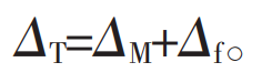
For tooth surface contact temperature: Δ T. Mainly determined by the temperature of spur gear body Δ M and tooth surface flash temperature Δ F is composed of two parts, namely:
Spur gear body temperature Δ M is generally assumed to be constant, and the tooth surface temperatures of the driving and driven wheels are consistent, while the tooth surface flash temperature Δ F is:
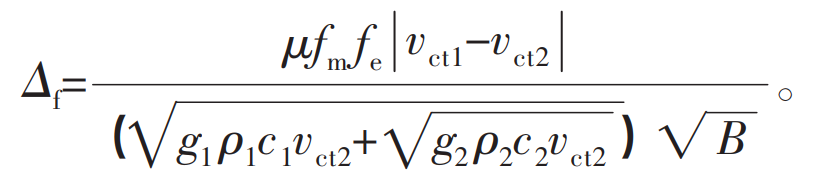
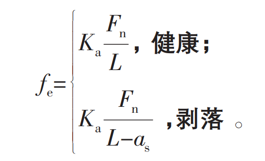
Where: μ Is the temperature rise coefficient; FM is the friction coefficient of the tooth surface; Fe is the normal load per unit tooth width; G1 and G2 are the heat conduction coefficients of main and driven wheels respectively; ρ 1 and ρ 2 density of main and driven wheels respectively; C1 and C2 are the specific heat capacities of the main and driven wheel materials respectively; B is the half width of contact band calculated by Hertz contact theory; Vct1 and vct2 are the tangential slip speeds of the two gears respectively. The calculation formula of tooth profile error is:
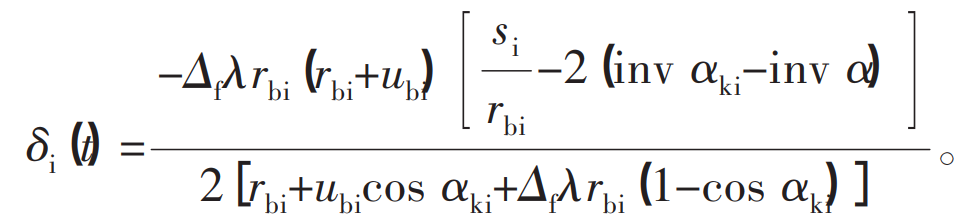
Where: λ Is the linear expansion coefficient of the material; Si is the tooth thickness on the indexing circle of spur gear; inv α Is an involute function; UBI is the thermal deformation of spur gear base circle. The calculation formula of normal load Fe on unit tooth width is:
According to Hertz contact theory, the flash temperature stiffness is:
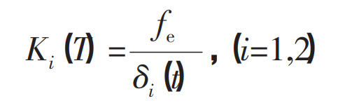
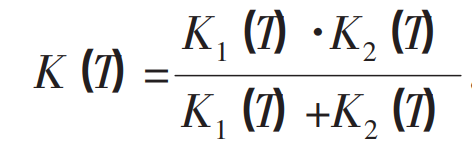
Wherein the flash temperature stiffness K (T) of spur gear pair is: