
1. Shell stiffness optimization
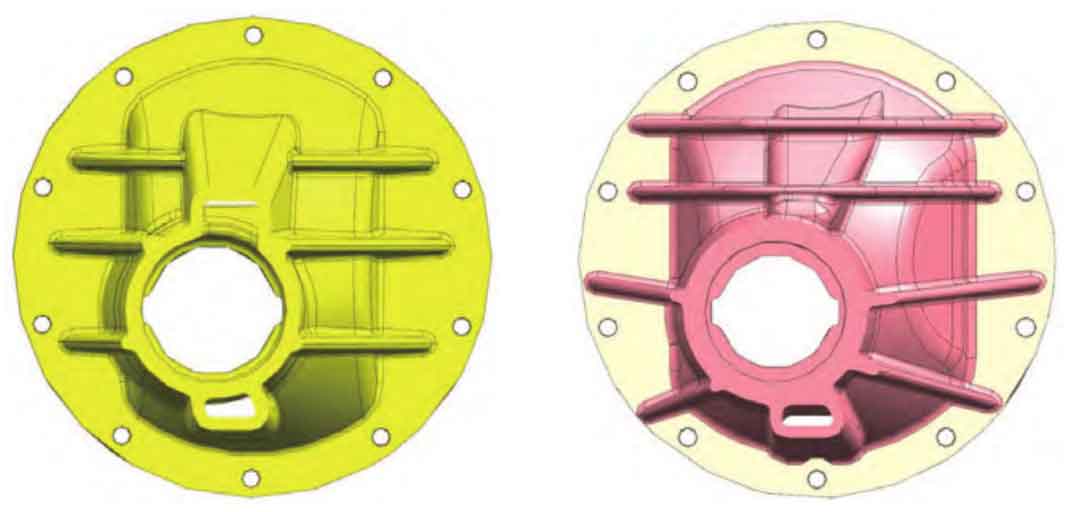
Re optimize the reinforcing rib on the main reducer housing. Adjust the thickness of the reinforcing rib from 5mm to 6mm, rearrange the direction of the reinforcing rib according to the structure, change the horizontal horizontal arrangement to the radial arrangement along the center of the main gear, and add a reinforcing rib in the horizontal direction. As shown in FIGS. 1a-b.
Use ABAQUS software to conduct CAE analysis on the shell stiffness before and after optimization, as shown in Fig. 2a-b. The detailed comparison results of the radial stiffness of the two shells before and after optimization are shown in Table 1.
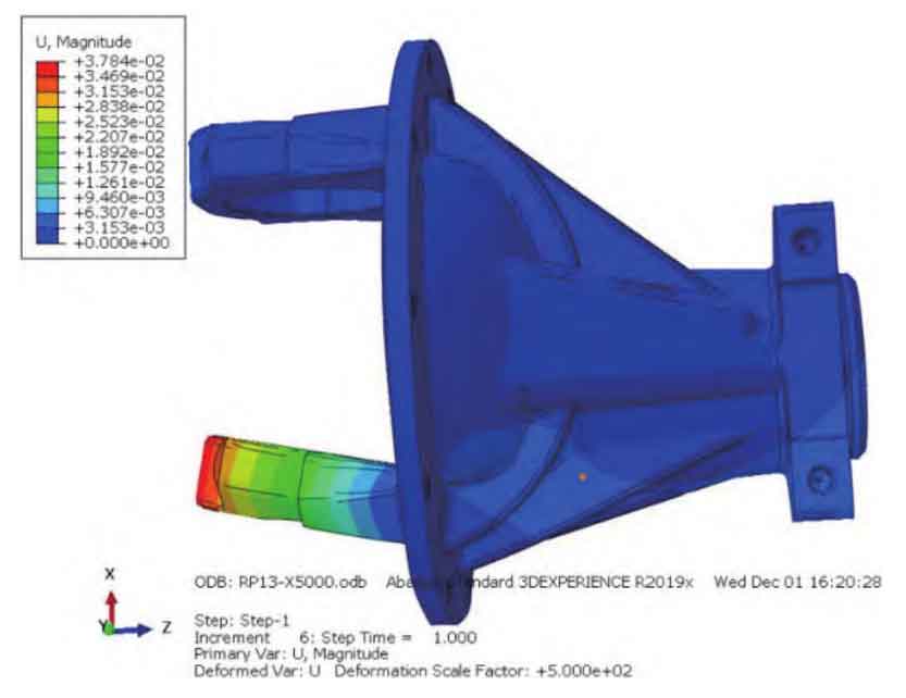
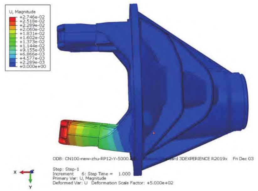
| Reduction shell | Differential shell | |
| Original state | 1779940 | 273399 |
| After optimization | 2421470 | 330865 |
| Increase of stiffness | 36% | 21% |
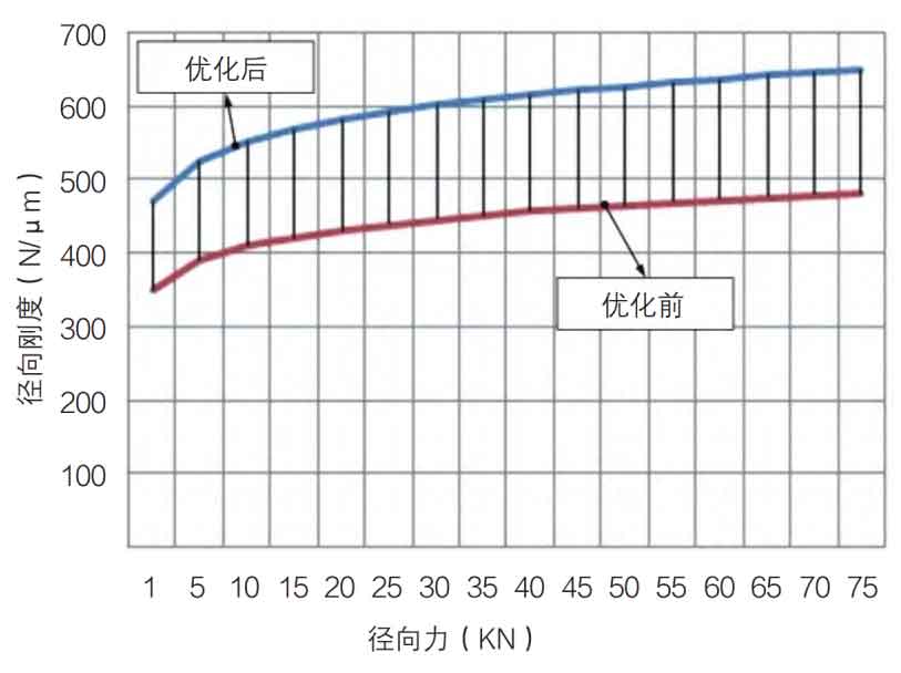
2. Optimization of bearing stiffness
The axial and radial stiffness of the bearing is improved by optimizing the structure of the bearing roller, raceway and flange. The radial stiffness before and after optimization is shown in Fig. 3. And increase the axial preload of the bearing to reduce the displacement of the spiral bevel gear during operation.
3. Parameter optimization of spiral bevel gear
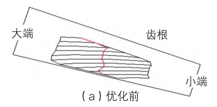
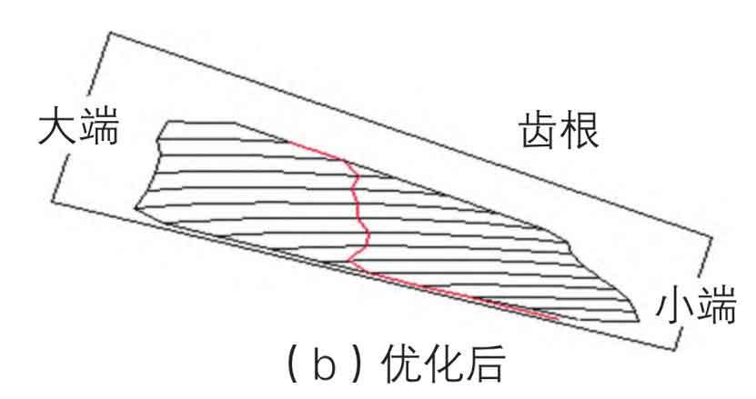
By adjusting the relevant parameters of the spiral bevel gear, the contact area of the spiral bevel gear is optimized, and the transmission error of the spiral bevel gear is reduced. After optimization, the contact area of spiral bevel gear increases by 40% compared with that before optimization, as shown in Fig. 4a-b. The design transmission error of spiral bevel gear is reduced by 50%, as shown in Fig. 5a-b.
4. Optimization of tie rod structure
Using ABAQUS software to analyze the mode of the tie rod, the bending mode of the tie rod in the Z direction of the rear axle is close to the bending mode of the tie rod in the X direction of the rear axle. The two are prone to resonance. The noise of the rear axle spiral bevel gear will be amplified and transmitted to the vehicle body, and the noise will be transmitted to the vehicle through the vehicle body. The cross section of the tie rod is optimized from U-shape to O-shape, so that the modes of the tie rod and the rear axle are staggered to avoid resonance. The mode distribution before and after optimization is shown in Table 2.
| Tie rod | Tie rod | Rear axle | Rear axle | |
| X | Z | X | Z | |
| Original state | 57 | 69.6 | 68 | 74.6 |
| After optimization | 60 | 84.6 | 66 | 73.5 |